
Building system and components therefor

Inactive Publication Date: 2012-01-19
RIVELLINO ERNEST
View PDF24 Cites 10 Cited by
  • Summary
  • Abstract
  • Description
  • Claims
  • Application Information

AI Technical Summary

Benefits of technology

[0009]The present invention provides a low cost, efficient unibody building construction that uses no nails, no wood, no drywall, trusses or concrete slabs; a building that can be made in weeks, not months or years with little or no waste and construction debris. The building is a low maintenance, ecology friendly design with no toxic emissions that provides all the amenities of much higher cost building. The building system and components for the construction of residential housing, industrial and commercial buildings and other type structures are made with pultrusion technology. Pultrusion is a process of heating, pressing and pulling composite material using pultruded polymer compounds such as polyurethane and reinforced by fiberglass or the like. The reinforced material is pulled through a specifically custom shaped die to create building materials used in the building of the invention and in the process for making the same. The building is formed with a plurality of pultrusion components bonded together to form a unitized structure. The building materials used in the present system include a main perimeter sill beam that is attached to foundation support columns; structural, foam insulated floor, wall and roof panels; corner connectors; a structural one-piece coved “wind spoilersoffit and fascia tie beam; and, a structural one piece ridge beam. The components are designed to be interconnected with adjacent, mating parts as the building is assembled. These interconnecting parts are bonded together into place using high strength resin adhesives.
[0012]Still another object is the provision of a low cost, low maintenance building that is easy to build and inexpensive to maintain.

Problems solved by technology

The need for low cost housing has been a primary concern for a number of years particularly in underdeveloped countries where costs, skilled labor and access to building materials present a considerable barrier to these programs.

Method used


Image

  • Building system and components therefor
  • Building system and components therefor
  • Building system and components therefor

Examples


Embodiment Construction

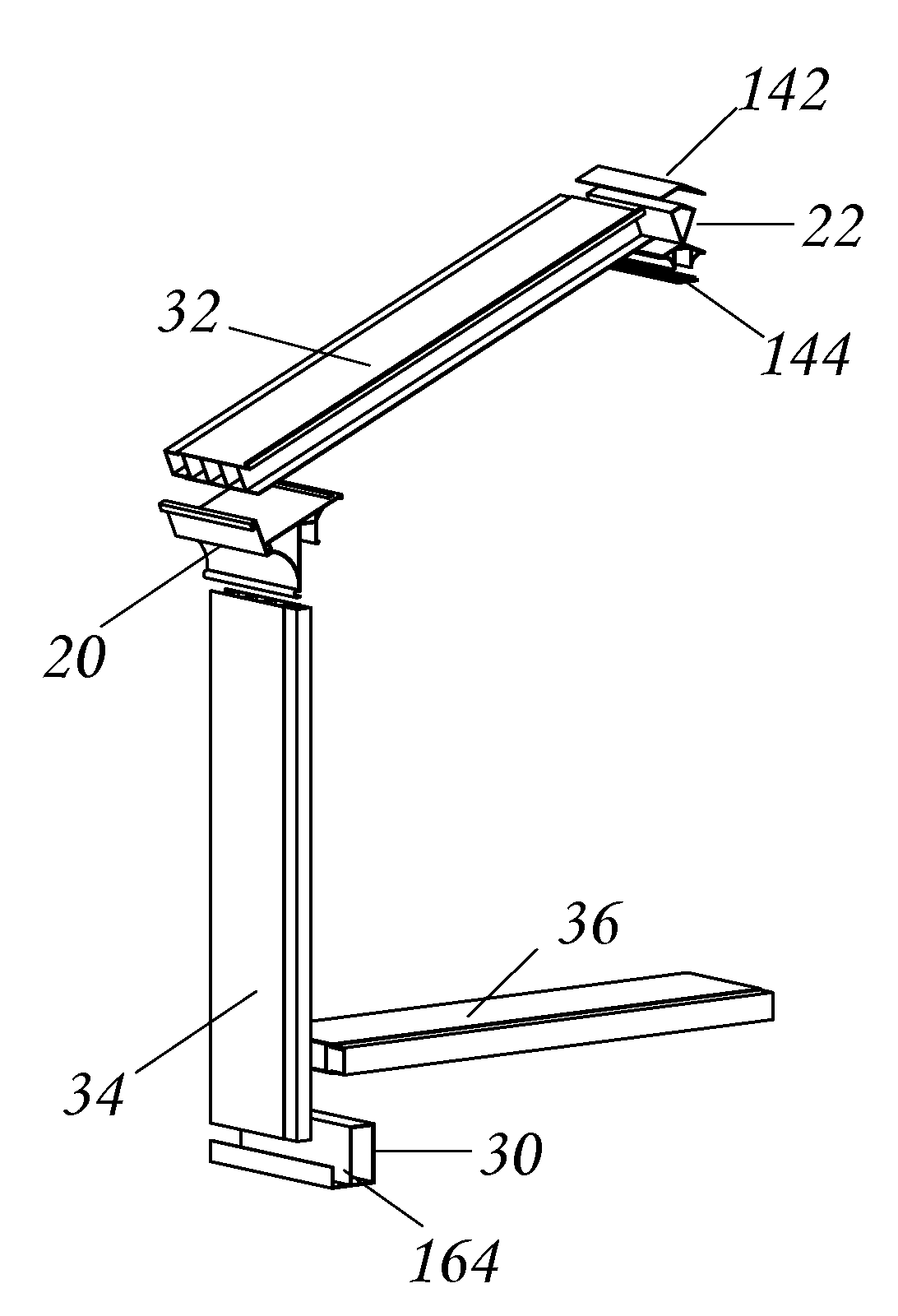
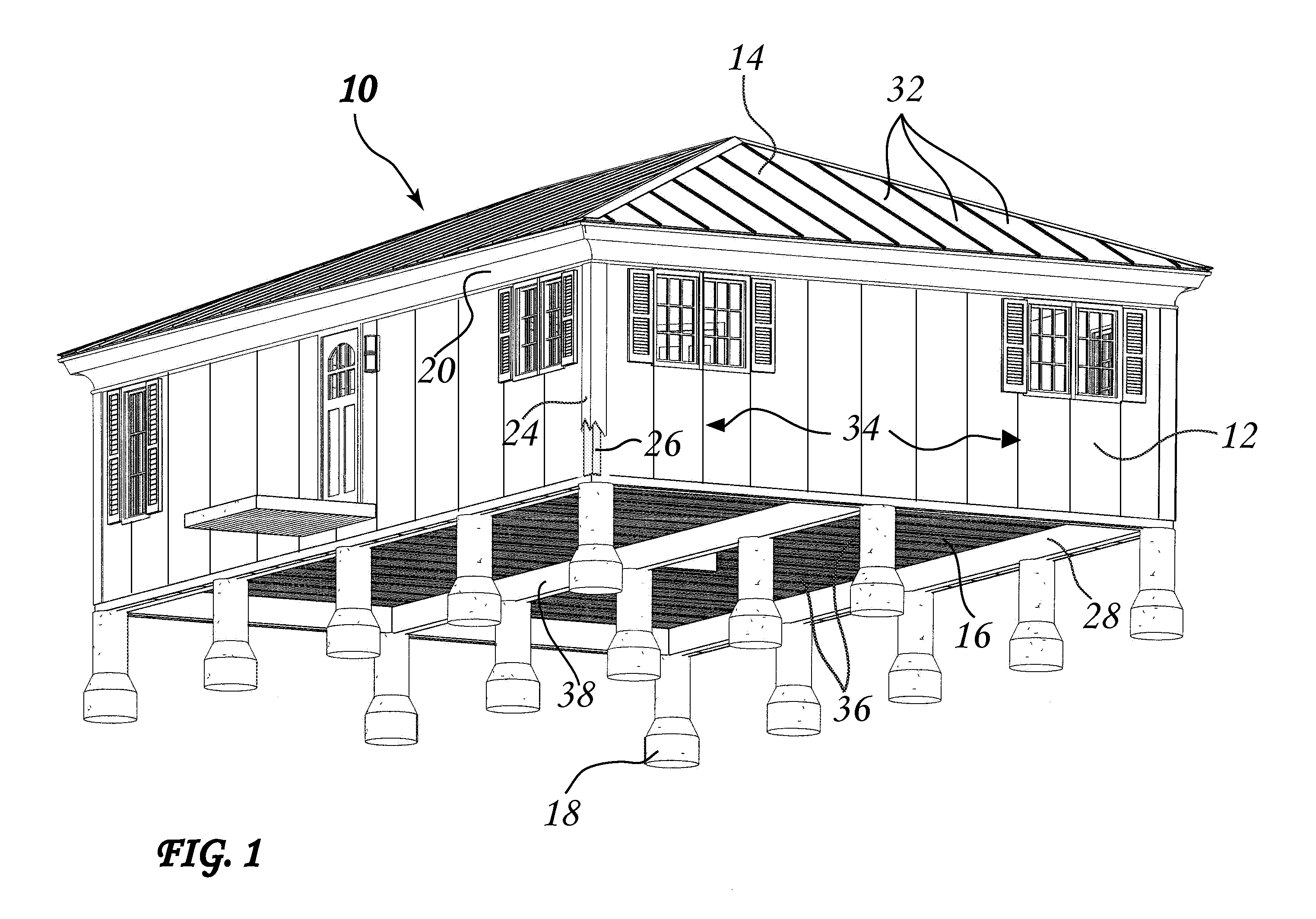
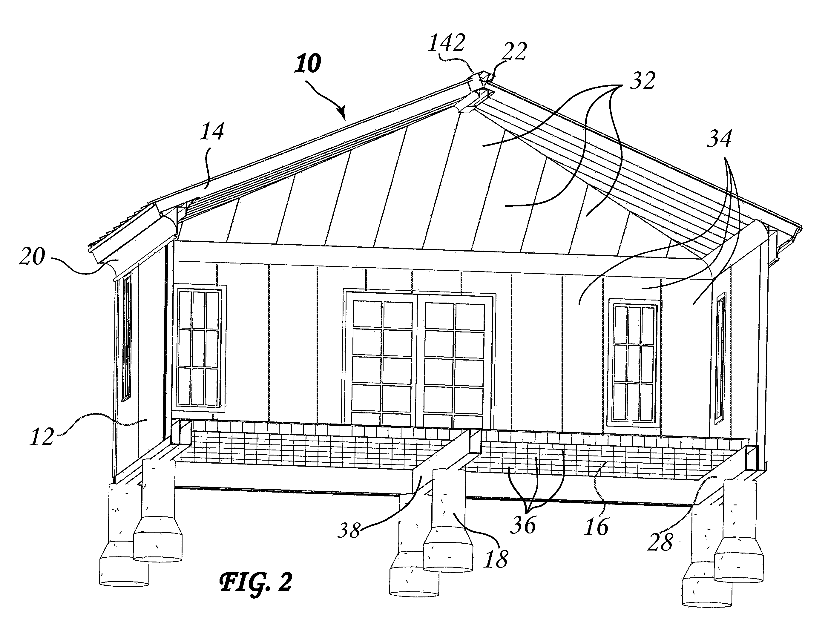
[0044]FIGS. 1 and 2 illustrate a typical building 10 made in accordance with the present invention having walls 12, a roof 14, floor 16 and foundation column supports 18. As seen in the sectional view of FIG. 2, the building 10 includes a soffit and fascia tie beam 20 connecting the roof 14 and walls 12, a structural ridge 22 at the top of the building 10 at the upper junction of the roof 14, an exterior corner cap 24, a corner connector 26, and sill beam 28 attached to the column supports 18. The roof 14 is made of a plurality of interconnected panels 32. Similarly the walls 12 are made of a plurality of interconnected panels 34. The floor 16 is also made with a plurality of interconnected panels 36. The corner connector 26 connects the wall panels 34 at the outside and inside corners of the wall junctions. The exterior corner cap 24 is positioned over the corner connector 26. An additional structural beam 38 is centrally located in the building 10 to support the floor 16 on the fo...


PUM

PropertyMeasurementUnit
Lengthaaaaaaaaaa
Structureaaaaaaaaaa
Strengthaaaaaaaaaa

Abstract

A unitized building construction formed of a plurality of pultruded building components adhesively connected. The building components include a ground support foundation, a main perimeter sill beam that is attached to the support columns; structural, foam insulated floor, wall and roof panels; structural corner connectors; a structural one-piece coved “wind spoilersoffit and fascia tie beam; and, a structural one piece ridge beam. The components are designed to be interconnected with adjacent parts as the building is assembled. These interconnecting parts are bonded together into place using high strength resin adhesives.

Description

PROVISIONAL APPLICATION[0001]The present invention was shown and described in a provisional application filed Jul. 16, 2010BACKGROUND OF THE INVENTION[0002]The need for low cost housing has been a primary concern for a number of years particularly in underdeveloped countries where costs, skilled labor and access to building materials present a considerable barrier to these programs. Various efforts have been made in the area of modular housing with a wide variety of levels of success. For example the following US patents are representative of the known prior art.[0003]U.S. Pat. No. 7,930,861 to Schiffmann et al shows a building system with walls, ceiling and a floor structure that is insulated with foam and made with pultruded materials.[0004]U.S. Pat. No. 6,901,710 to Cooper discloses a fiberglass reinforced, pultruded vault construction using prefabricated wall, ceiling and floor panels made from pultruded material that are bonded together with adhesive.[0005]U.S. Pat. No. 6,941,7...

Claims


Application Information

Patent Timeline
IPC IPC(8): E04B1/19E04B1/00E04B1/38
CPCE04B1/12E04D3/40E04D3/32E04B1/4157
Inventor RIVELLINO, ERNEST
Owner RIVELLINO ERNEST
Features
  • Generate Ideas
  • Intellectual Property
  • Life Sciences
  • Materials
  • Tech Scout
  • Unparalleled Data Quality
  • Higher Quality Content
  • 60% Fewer Hallucinations
Learn More