
Battery pack fault communication and handling

a battery pack and fault technology, applied in relays, electrochemical generators, safety/protection circuits, etc., can solve the problems of complex computer systems, electric vehicles with modular batteries, and use of electric vehicles, and achieve the effect of preventing the heartbeat signal

Active Publication Date: 2012-01-19
SINOELECTRIC POWERTRAIN
View PDF9 Cites 59 Cited by
  • Summary
  • Abstract
  • Description
  • Claims
  • Application Information

AI Technical Summary

Benefits of technology

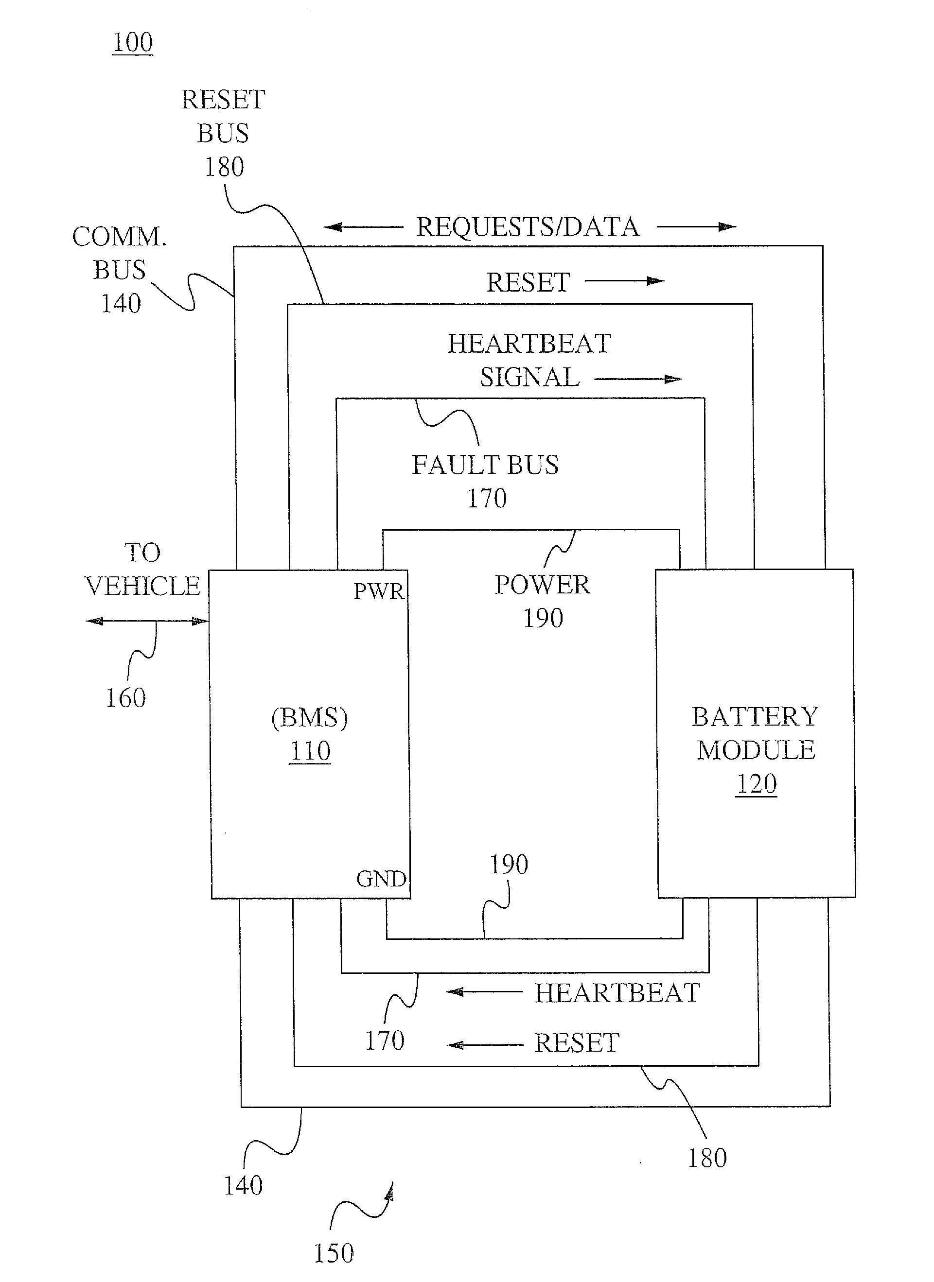
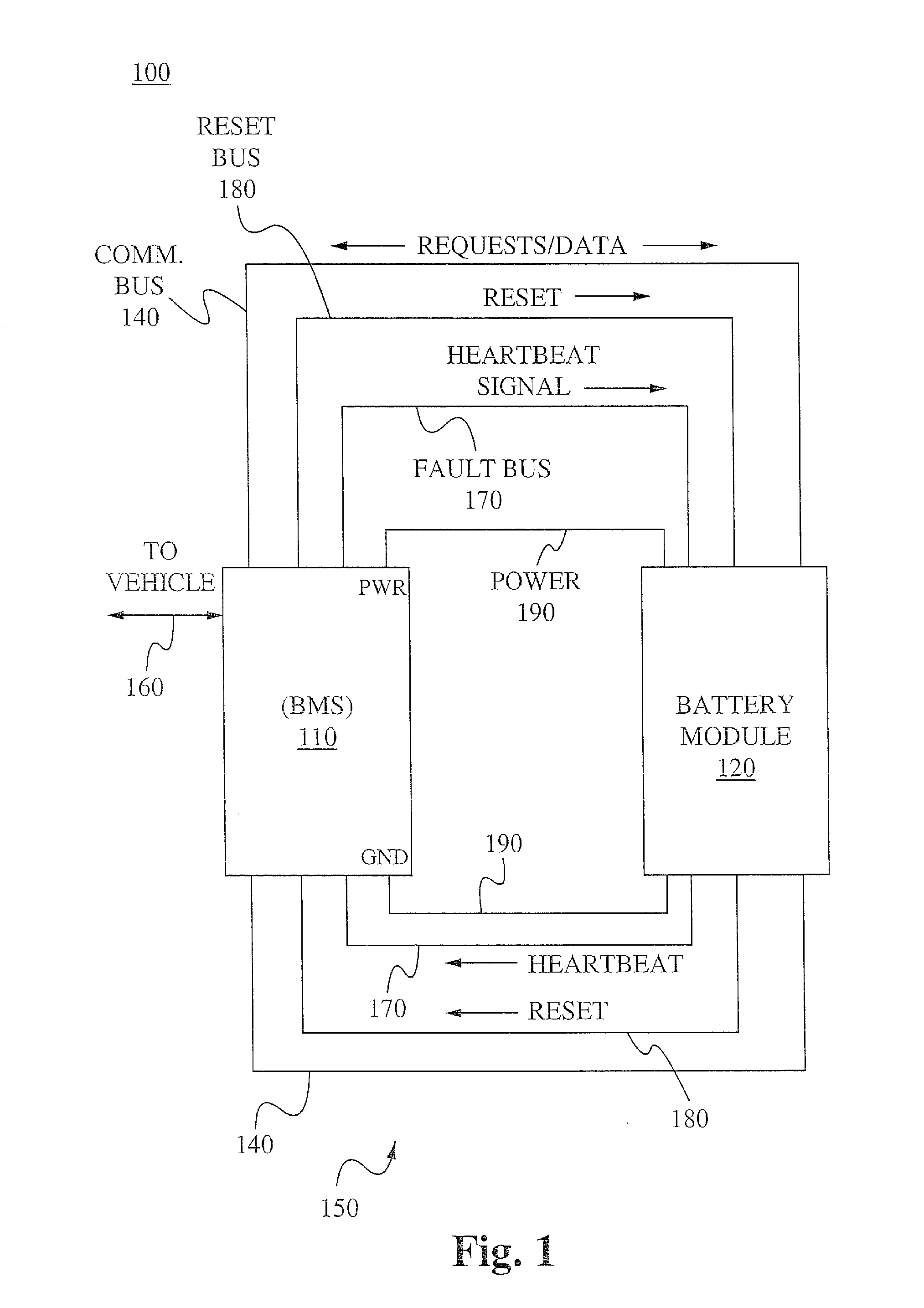
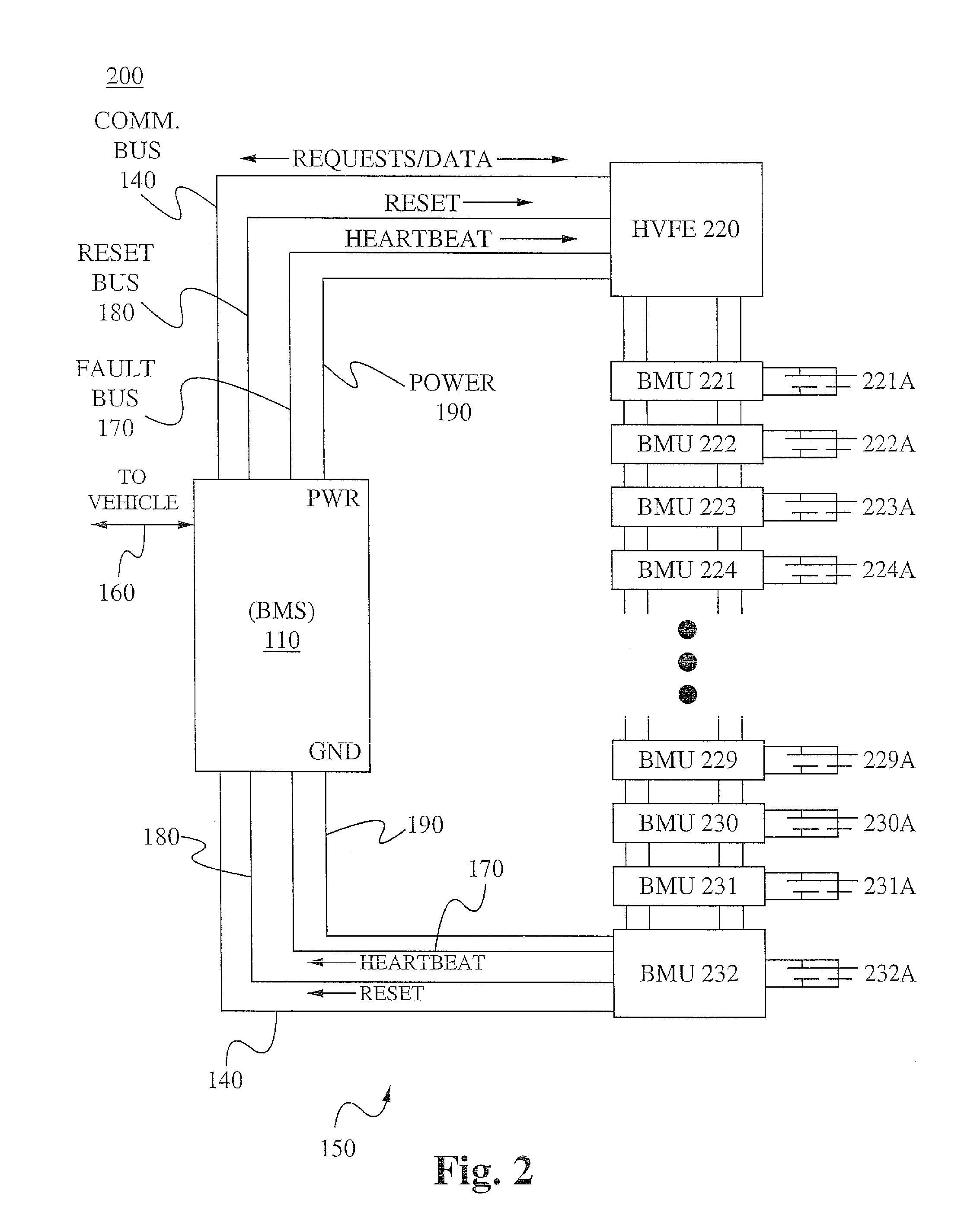
[0012]In some embodiments, the communication bus is a CAN-bus. In some embodiments, the one or more commands comprises a command to open or close a contactor for at least one of the batteries. In some embodiments, the BMS is configured to ping the BMUs via the communication bus in response to one of BMUs preventing the BMS from receiving the heartbeat signal.
[0013]In some embodiments, the system further comprises a reset bus coupled between the BMS and the plurality of BMUs. The reset bus is distinct from the communication bus, and the BMS is configured to perform a hardware reset on all of the BMUs via the reset bus. In some embodiments, the BMS is configured to perform a hardware reset on all of the BMUs via the reset bus in response to a reset condition, and the reset condition comprises one of the BMUs preventing the BMS from receiving the heartbeat signal. In some embodiments, the reset condition further comprises the BMS attempting to communicate with the BMUs via the communication bus after one of the BMUs prevents the BMS from receiving the heartbeat signal. In some embodiments, the BMS is configured to apply a reset signal to the plurality of BMUs via the reset bus for a period of time. The reset signal is configured to shut off the BMUs. In some embodiments, the period of time during which BMS applies the reset signal lasts until after the BMS receives an indication that all of the BMUs have been reset. In some embodiments, the period of time during which BMS applies the reset signal lasts until a predetermined amount of delay time after the BMS receives an indication signal via the reset bus that all of the BMUs have been reset.
[0014]In yet another aspect of the present invention, a method of handling a fault in a battery pack is provided. The method comprises a battery module supplying a voltage to a high-voltage circuit, a BMS transmitting a heartbeat signal to the battery module via a fault bus, the battery module preventing the heartbeat signal from being transmitted back to the BMS in response to the battery module detecting a critical condition, and the BMS shutting off the supply of voltage from the battery module to the high-voltage circuit in response to the battery module preventing the heartbeat signal from being transmitted back to the BMS. In some embodiments, the high-voltage circuit incorporated into a vehicle.
[0015]In some embodiments, the critical condition comprises one of overcharging a battery cell, over-discharging a battery cell, an isolation fault, a short-circuit, over-current, over-temperature, or over-power. In some embodiments, preventing the heartbeat signal from being transmitted back to the BMS is performed using an open-collector, an open-drain transistor, a diode, or a relay.
[0016]In some embodiments, the method further comprises the battery module transmitting battery data to

Problems solved by technology

However, the use of electric vehicles presents technical challenges.
Electric vehicle having modular batteries can be particularly challenging, as they have multiple batteries or battery packs that must be monitored and managed.
Battery monitoring systems in current vehicles are generally complex computer systems.
Such systems are inherently complex and require dedicated software systems that must be made sufficiently robust since a failure of the battery monitoring system may cause the electric vehicle to stop functioning.
Therefore, significant time and effort must be placed into software and operating system development for battery monitor systems.
As a result, product cycle time and cost are greatly increased.

Method used


Image

  • Battery pack fault communication and handling
  • Battery pack fault communication and handling
  • Battery pack fault communication and handling

Examples


Embodiment Construction

[0023]The following description is presented to enable one of ordinary skill in the art to make and use the invention and is provided in the context of a patent application and its requirements. Various modifications to the described embodiments will be readily apparent to those skilled in the art and the generic principles herein may be applied to other embodiments. Thus, the present invention is not intended to be limited to the embodiment shown but is to be accorded the widest scope consistent with the principles and features described herein.

[0024]Various aspects of the disclosure may be described through the use of flowcharts. Often, a single instance of an aspect of the present disclosure may be shown. As is appreciated by those of ordinary skill in the art, however, the protocols, processes, and procedures described herein may be repeated continuously or as often as necessary to satisfy the needs described herein. Additionally, it is contemplated that certain method steps of ...


PUM


Abstract

A method of handling a fault in a battery pack, the method comprising: a battery module supplying a voltage to a high-voltage circuit; a battery management system transmitting a heartbeat signal to the battery module via a fault bus; the battery module preventing the heartbeat signal from being transmitted back to the battery management system in response to the battery module detecting a critical condition; and the battery management system shutting off the supply of voltage from the battery module to the high-voltage circuit in response to the battery module preventing the heartbeat signal from being transmitted back to the battery management system. The battery module transmits battery data to the battery management system via a communication bus, which is distinct from the fault bus, and the battery management system transmits one or more commands to the battery module via the communication bus.

Description

CROSS-REFERENCE TO RELATED APPLICATIONS[0001]This application claims priority to co-pending U.S. Provisional Patent Application Ser. No. 61 / 364,313, filed Jul. 14, 2010 and entitled “BATTERY MONITOR SYSTEM FOR AN ELECTRIC VEHICLE,” which is hereby incorporated by reference in its entirety as if set forth herein.FIELD OF THE INVENTION[0002]The present invention relates to managing batteries for electric vehicles. More specifically, the present invention relates to fault communication and handling for a battery pack.BACKGROUND OF THE INVENTION[0003]For a multitude of reasons, it is advantageous to use electric vehicles having rechargeable batteries rather than vehicles using internal combustion engines. Electric vehicles are inherently more efficient, meaning more energy is used in locomotion than lost to heat than in conventional internal combustion engines. Also, electric vehicles do not exhaust any byproducts. However, the use of electric vehicles presents technical challenges. For...

Claims


Application Information

Patent Timeline
IPC IPC(8): H02J7/00
CPCH01M10/48H02J2007/0098H02J7/0029H01M10/4257Y02E60/10
Inventor PARISEAU, DAVID KEVINWANG, YANGCOLLINS, MICHAEL KEITHZHOU, PENG
Owner SINOELECTRIC POWERTRAIN
Learn More