Spd films and light valve laminates with improved durability

a technology of spd films and laminates, applied in the field of spd films and light valve laminates with improved durability, can solve the problems of interlayer materials and inability to possess moisture resistance properties, light frame appearance, and the tendency of cured emulsions to absorb moisture through the exposed edge of spd films, so as to reduce the migration of moistur

Active Publication Date: 2012-01-19
RES FRONTIERS
View PDF9 Cites 31 Cited by
  • Summary
  • Abstract
  • Description
  • Claims
  • Application Information

AI Technical Summary

Benefits of technology

[0025]As noted above, the moisture content of interlayer material(s) used in forming the SPD laminate is reduced as far as practicable to prevent, or at least reduce, migration of moisture into the film. Suitable interlayer materials for use in SPD laminates include, but are not limited to, ethylene vinylacetate, polyvinylbutyral and polyurethane.

Problems solved by technology

As mentioned above, prolonged exposure of SPD film or laminates of SPD film to elevated temperatures and / or humidity can cause a light frame to appear.
However, the tape in that instance was used as a physical barrier to the interlayer material and did not possess moisture resistant properties.
Another deficiency of prior art SPD films was the tendency of the cured emulsion to absorb moisture through the exposed edge of the SPD film over time if measures were not taken to isolate the SPD film from sources of such moisture.
Subsequent exposure of the SPD film or laminates of the SPD film to elevated temperatures and / or humidity could lead to a defect such as the light frame mentioned above.
However, this application does not consider the moisture content in the SPD film itself, moisture-resistant barrier materials to prevent moisture from contacting the SPD film or moisture-resistant border materials to prevent moisture from entering the SPD laminate.

Method used


Image

  • Spd films and light valve laminates with improved durability
  • Spd films and light valve laminates with improved durability
  • Spd films and light valve laminates with improved durability

Examples


Embodiment Construction

[0029]SPD films and laminates incorporating such SPD films were exposed to elevated temperatures under the given conditions and the following results were observed:

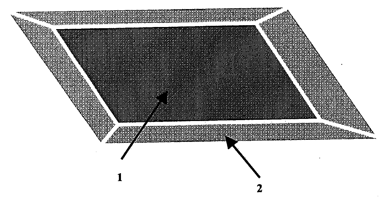
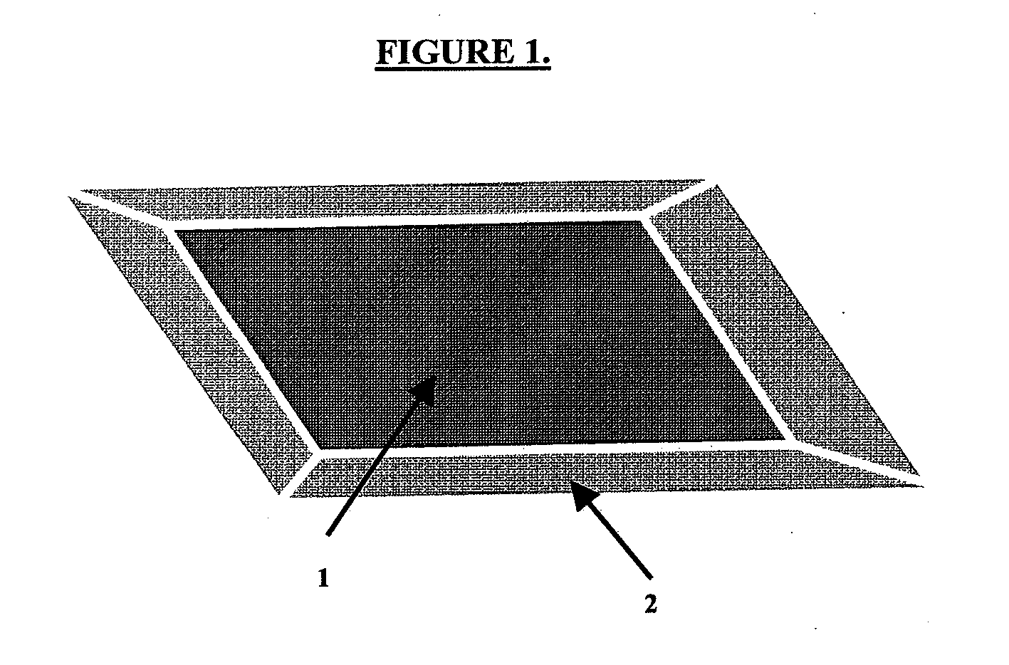
[0030]SPD films exposed to a 100° C. oven at ambient humidity developed a light frame in 4 days.

[0031]SPD films placed in a vacuum desiccator with a vacuum of approximately 0.001 Ton were exposed to an 80° C. oven for 4 days followed by a 90° C. oven for 14 days whereupon no light frame was observed. This demonstrates that the combination of moisture (from the air) and elevated temperatures was responsible for the appearance of the light frame, with the moisture being the major factor.

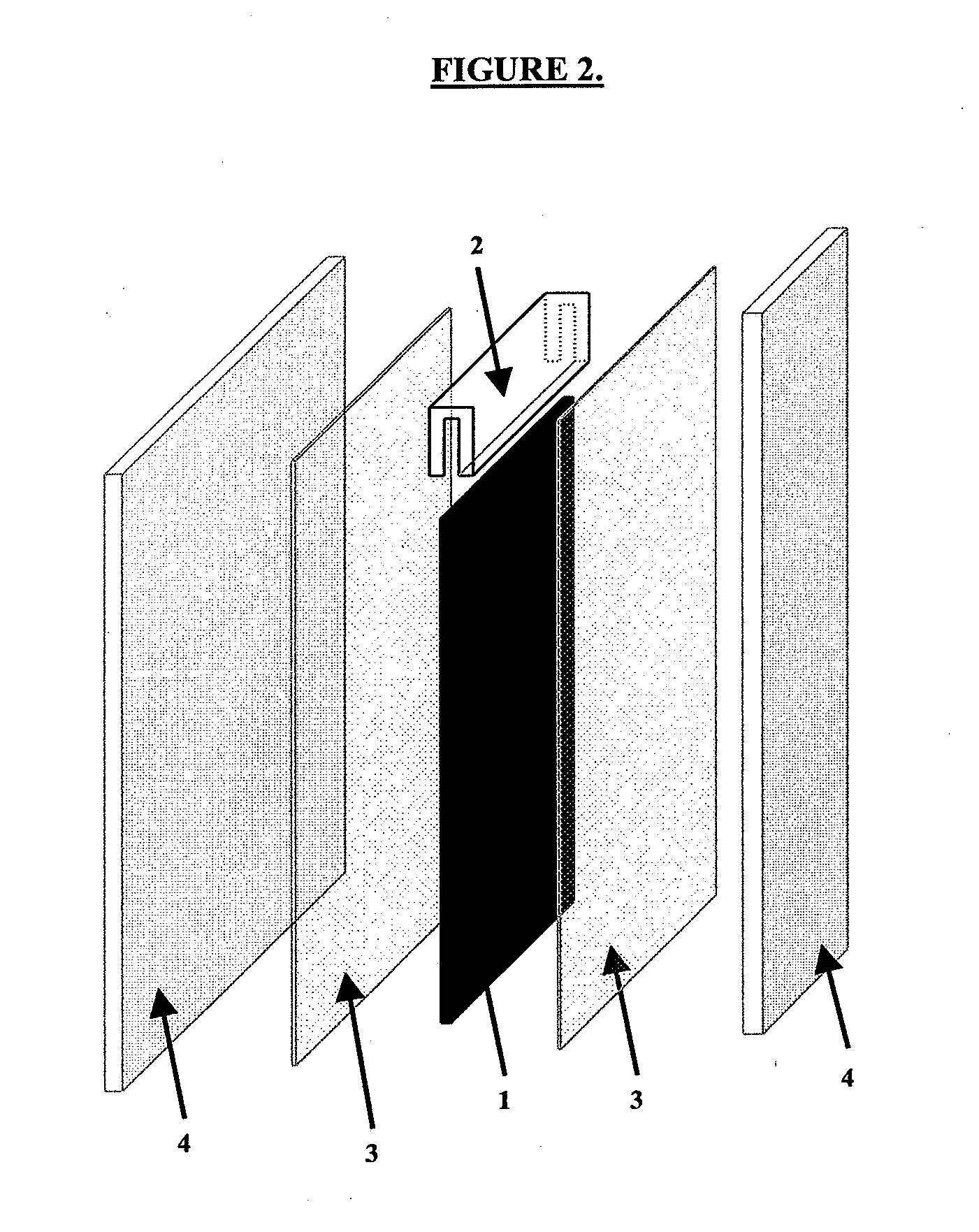
[0032]SPD films that were laminated between two plies of glass with sheets of interlayer material, using the laminating conditions described in U.S. Pat. No. 7,361,252, assigned to the assignee of the present invention, did not develop a light frame. However, exposure of these SPD laminates to a 100° C. oven did result in the appearance of a...


PUM

PropertyMeasurementUnit
thicknessaaaaaaaaaa
thicknessaaaaaaaaaa
thickaaaaaaaaaa

Abstract

A moisture-resistant suspended particle device film comprising a cured suspended particle device emulsion having a plurality of uncrosslinked droplets of a liquid light valve suspension distributed throughout the cured emulsion; first and second glass or plastic sheets located outwardly from and sandwiching the cured emulsion, wherein located on an inner aspect of each sheet, adjacent the cured emulsion, is a thin, transparent, electrically conductive coating , the coating serving as an electrode to permit passage of an applied electric field through the cured emulsion; and a moisture-resistant barrier located around an entire outer peripheral edge portion of the film, wherein the barrier is comprised of a barrier material that eliminates or at least reduces passage of moisture from outside the film into the cured emulsion, thus preventing development of a light-frame pattern in the film that would otherwise be caused by the moisture. The disclosure also discloses forming a laminate comprising the above-described film, as well as methods of forming such films and laminates.

Description

CROSS-REFERENCE TO RELATED APPLICATION[0001]This application is based on and claims priority to U.S. Provisional Patent Application Ser. No. 61 / 363,934, filed on Jul. 13, 2010 and entitled “SPD FILMS AND LIGHT VALVE LAMINATES WITH IMPROVED DURABILITY,” the entire contents of which are hereby incorporated by reference.FIELD OF THE INVENTION[0002]The invention is directed to films and laminates of films for use in light valves comprising liquid particle suspensions, which light valves are generally referred to herein as suspended particle devices or SPD light valves, or simply as SPDs. The SPD film is treated to remove trapped moisture, followed by the application of means for preventing moisture from entering the edge of the SPD film pre- and, optionally, post-lamination.BACKGROUND OF THE INVENTION[0003]SPD light valves have been known for more than seventy years for use in the modulation of light. Such light valves have been utilized in numerous applications during that time includi...

Claims


Application Information

Patent Timeline
Patent Type & Authority Applications(United States)
IPC IPC(8): H01R4/04B29C65/48
CPCB32B17/10036B32B17/10302B32B17/10532G02F1/172B32B17/1077B32B17/10788G02B1/105B32B17/10761B32B7/12B32B27/08B32B27/20B32B27/306B32B27/36B32B27/40B32B3/02B32B2255/10B32B2255/20B32B2307/40B32B2307/41B32B2307/412B32B2307/7246B32B2551/00G02B1/18G02B1/10G02B1/14
Inventor WANG, DONGYANSLOVAK, STEVEN M.SAXE, ROBERT L.CHEN, XIAO-PING
Owner RES FRONTIERS
Why Eureka
Try Eureka