Medical image dianostic device, region-of-interst setting method, and medical image processing device
a medical image and diagnostic device technology, applied in the field of medical image diagnosis devices, a region-of-interst setting method, and a medical image processing device, can solve problems such as burden on the examiner
- Summary
- Abstract
- Description
- Claims
- Application Information
AI Technical Summary
Benefits of technology
Problems solved by technology
Method used
Image

Examples
example 1
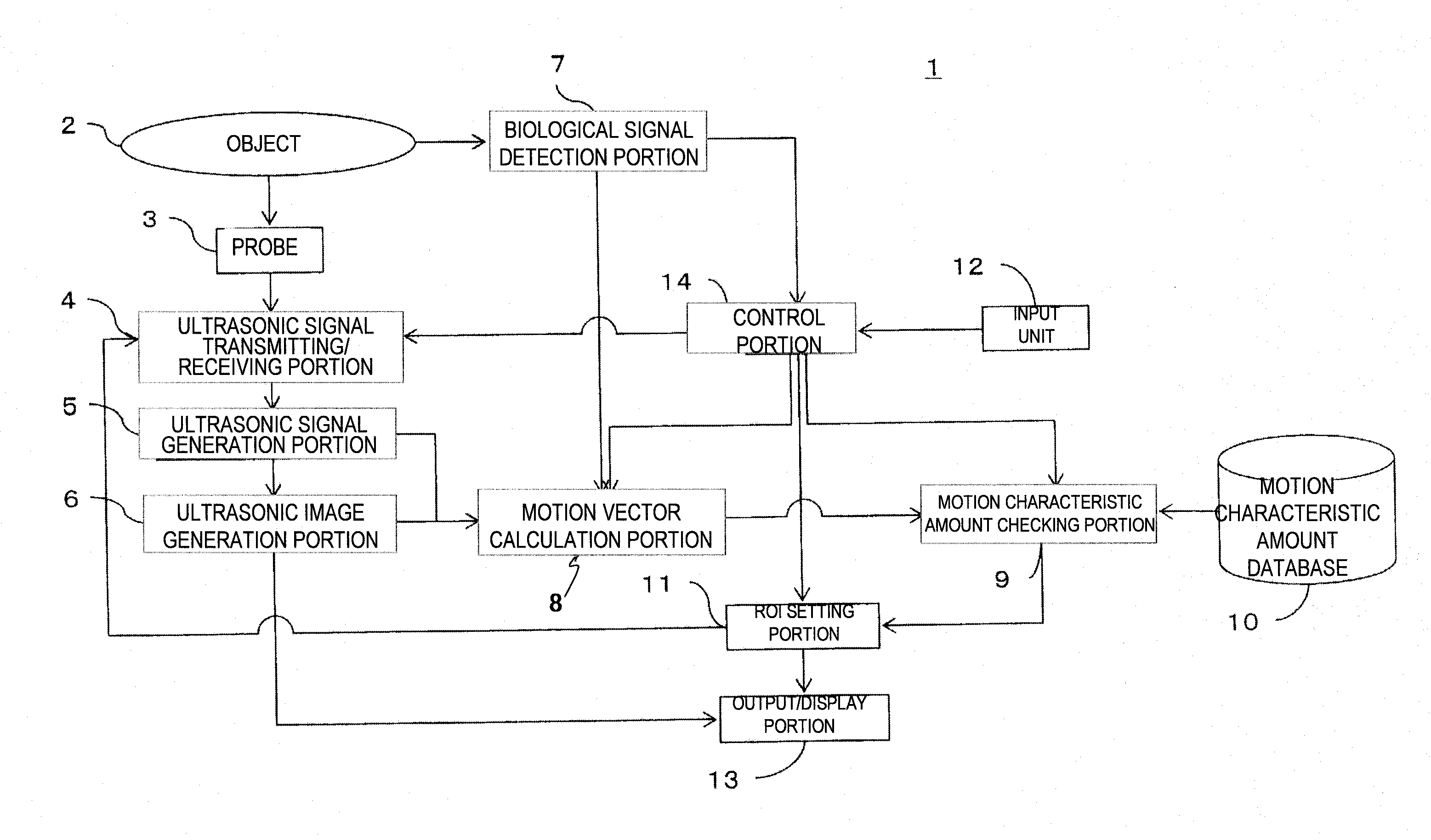
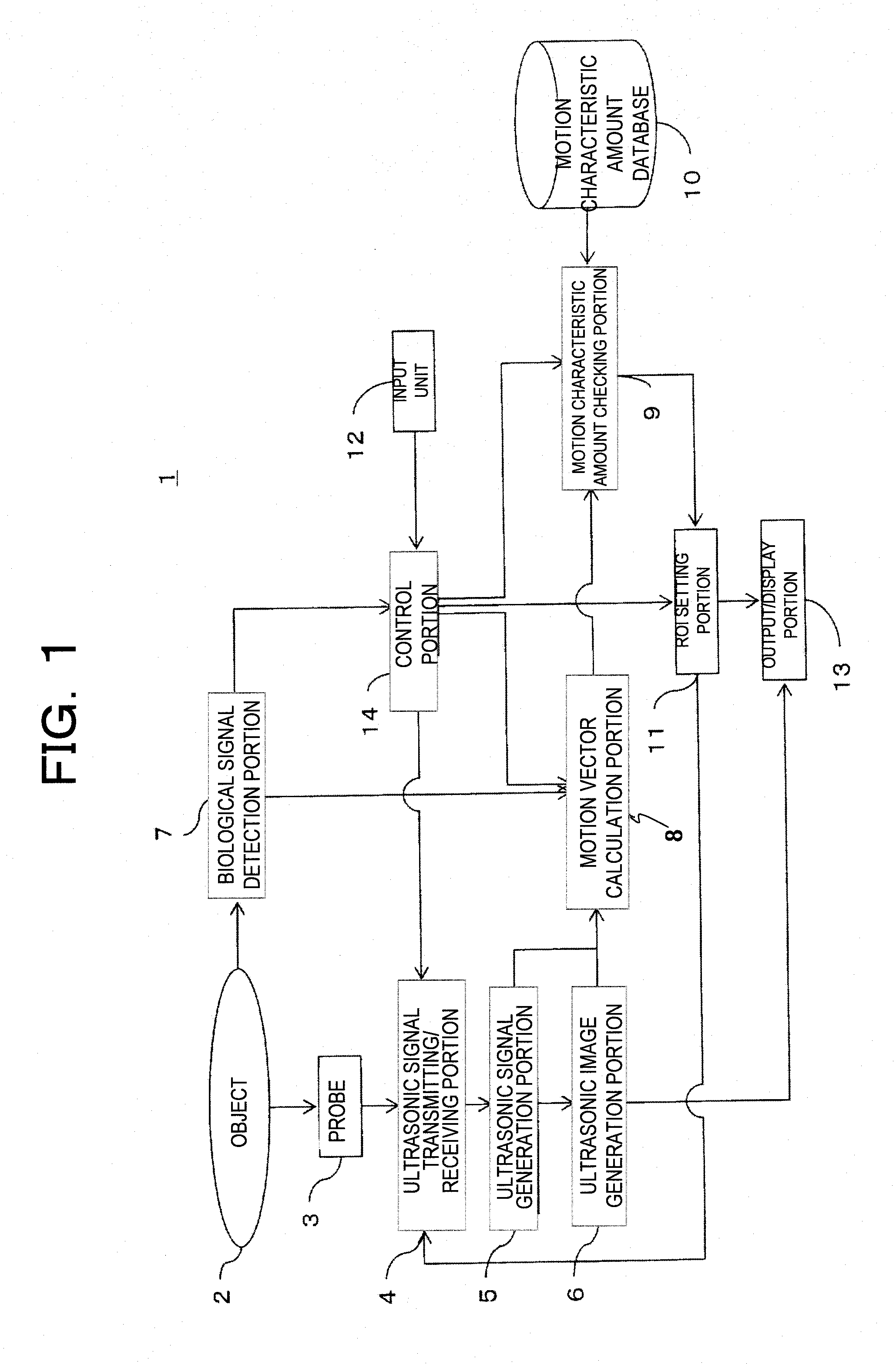
[0038]FIG. 1 is a block diagram showing a schematic configuration of Example 1 of the ultrasonic diagnosis device to which the invention is applied. An ultrasonic diagnosis device 1 shown in FIG. 1 is based on a well-known ultrasonic diagnosis device and makes an ultrasonic diagnosis by using two or three dimensional signals. The ultrasonic diagnosis device 1 includes a probe 3, an ultrasonic signal transmitting and receiving portion 4, an ultrasonic signal generation portion 5, an ultrasonic image generation portion 6, a biosignal detection portion 7, a motion vector calculation portion 8, a motion characteristic amount checking portion 9, a motion characteristic amount database 10, a ROI setting portion 11, an input portion 12, an output and display portion 13, and a control portion 14.
[0039]The probe 3 is a device which transmits and receives ultrasonic waves to and from an object 2 and converts the ultrasonic waves into electric signals. The probe 3 uses a linear type, a convex ...
example 2
[0070]Next, Example 2 of the ultrasonic diagnosis device to which the invention is applied will be described. The configuration of the ultrasonic diagnosis device of Example 2 is the same as Example 1. FIG. 9 is a flowchart of Example 2 of the ultrasonic diagnosis device. In Example 2, after the ROI is set in the same manner as in Example 1, a beam scanning range is narrowed down based on the set ROI, and the position of the ROI is caused to follow the tissue motion.
[0071]Steps S201 to S205 are the same as steps S101 to S105 of Example 1, hence the description thereof is omitted. Herein, a case of setting a ROI 902 at two locations in the short axis view of the heart in FIG. 8 will be described for example. The myocardium of the heart repeatedly contracts and dilates while moving as if it twists. Accordingly, for example, if a characteristic amount defined as vectors that move obliquely toward a lower left side (or move obliquely toward an upper right side) while rotating is stored ...
example 3
[0084]Next, Example 3 of the ultrasonic diagnosis device to which the invention is applied will be described. FIG. 13 is a block diagram showing a schematic configuration of the ultrasonic diagnosis device of Example 3. As shown in FIG. 13, in the ultrasonic diagnosis device 1 of the example, the motion vector calculation portion 8 of Example 1 is substituted with a brightness calculation portion 18, the motion characteristic amount checking portion 9 is substituted with a brightness characteristic amount checking portion 19, and the motion characteristic amount database 10 is substituted with a brightness characteristic amount database 20. Configurations other than these are the same as Example 1, so the descriptions thereof are omitted.
[0085]At timings and positions specified by the control portion 14, the brightness calculation portion 18 performs a statistical processing such as averaging, dispersion, and the like on a brightness distribution of plural measurement points of the ...
PUM
 Abstract
Description
Claims
Application Information
 - R&D
- Intellectual Property
- Life Sciences
- Materials
- Tech Scout
- Unparalleled Data Quality
- Higher Quality Content
- 60% Fewer Hallucinations
Browse by: Latest US Patents, China's latest patents, Technical Efficacy Thesaurus, Application Domain, Technology Topic, Popular Technical Reports.
© 2025 PatSnap. All rights reserved.Legal|Privacy policy|Modern Slavery Act Transparency Statement|Sitemap|About US| Contact US: help@patsnap.com