
Yieldable cone bolt and method of manufacturing same

a cone bolt and bolt head technology, applied in the field of ground control systems, can solve the problems of increasing the chance of contamination of the environment and other equipment by lubricant, increasing the possibility of bolt fracture and failure, and increasing the chance of contamination, so as to improve the debonding layer, and reduce the frictional resistance

Active Publication Date: 2012-01-19
DSI UNDERGROUND CANADA LTD SOUTERRAIN DSI CANADA LTEE
View PDF12 Cites 14 Cited by
  • Summary
  • Abstract
  • Description
  • Claims
  • Application Information

AI Technical Summary

Benefits of technology

[0012]Accordingly, an object of the invention is to provide a mine roof support system which includes a mixed resin composition, a tensionable nut, forged head, cable grip (hereinafter collectively and generally referred to as torquing or spinning mechanism) and a yieldable anchor assembly which includes a tendon provided with one or more covering sheaths used to prevent or limit chemical adhesion between the anchoring resin and the covered portions of the tendon.
[0028]By controlling the debonding length of the sheath, it is possible to easily adjust the pullout strength of bolt stiffness for different ground condition / application.

Problems solved by technology

In particular, if the bolt is unable to yield, the bolt may otherwise fracture and fail completely.
The applicant has appreciated various disadvantages exist with the installation and use of conventional cone bolts.
The packaging of cone bolts in crates immersed in grease, and the requirement to manually remove excess lubricant is both unpleasant to the installer and results in the increased possibility of contamination of both the environment and other equipment by the lubricant.
This furthermore increases the chance that the bolt and / or the bolt installation tool could slip from the installer's hands, leading to damage or injury.
In addition, the application of heavy grease coatings increases the possibility that dust, dirt and other debris typically present in mining environments could adhere to the bolt prior to its insertion.
Such debris may adversely contaminate the resin compositions, decreasing its effectiveness.
Analytical testing has suggested that the rotation of the bolt by itself within unset resin, frequently results in the lubricating grease being stripped entirely from the bolt surface, resulting in chemical bonding between the resin and the bolt, which could interfere with yielding movement.

Method used


Image

  • Yieldable cone bolt and method of manufacturing same
  • Yieldable cone bolt and method of manufacturing same
  • Yieldable cone bolt and method of manufacturing same

Examples


Embodiment Construction

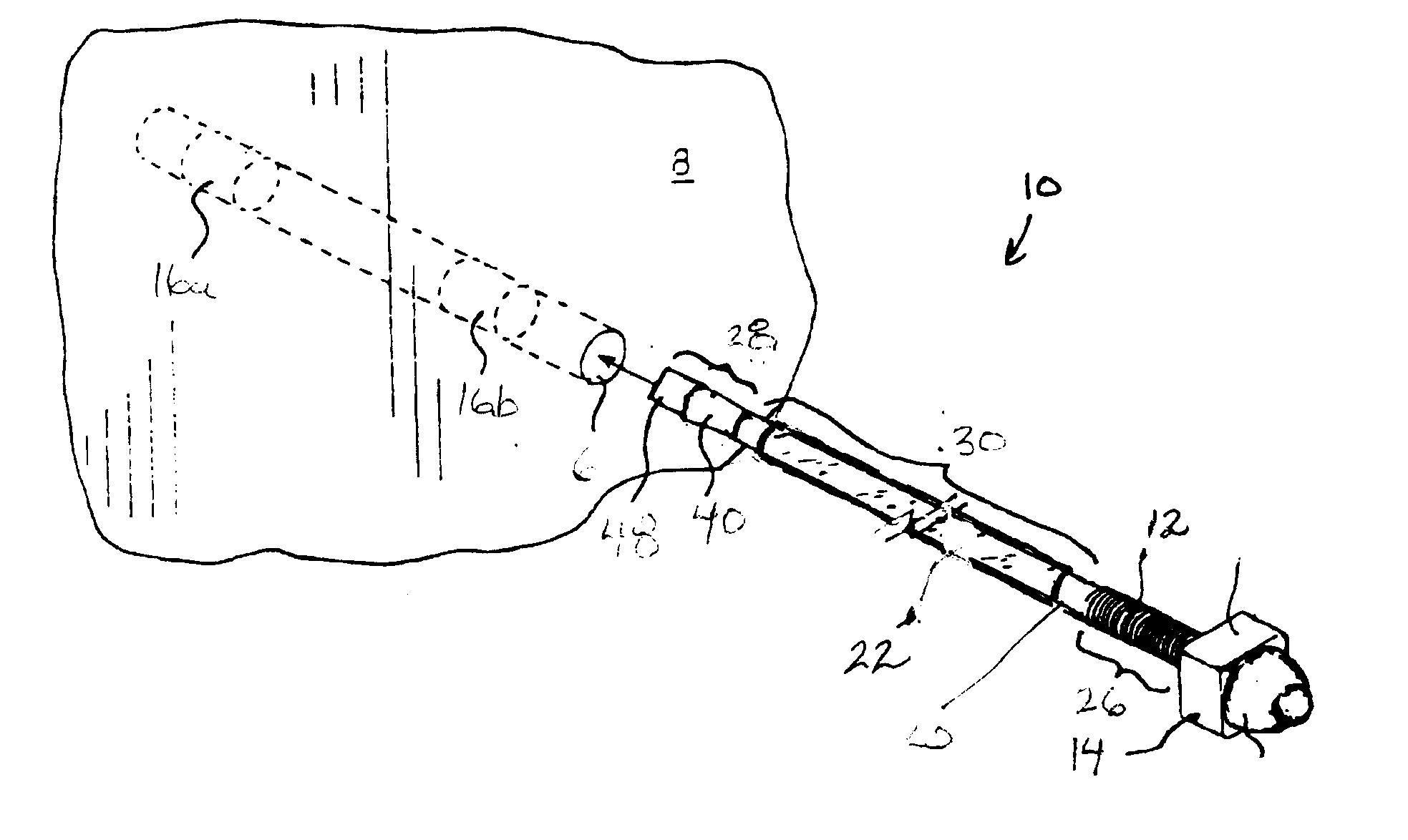
[0069]The present invention relates to a mine roof support assembly 10 which, as shown best in FIG. 4, is adapted for placement within a bore hole 6 formed in a rock complex 8. Depending upon the site of installation and geology, the bore hole 6 is predrilled into the rock complex 8 to a typical depth of between about 1.5 and 2 metres.

[0070]FIGS. 3 to 5 show the mine roof system 10 used to reinforce the rock complex 8 as including a cone bolt 12, a cast steel dome nut 14, and a series of two-part resin cartridges 16a, 16b which each carry a volume of unmixed two-part low viscosity resin 18 (FIG. 5). As will be described, the cone bolt 12 operates in conjunction with the dome nut 14 and resin cartridges 16a, 16b to achieve the mixing of the anchoring resin 18 within the bore hole 6, and the subsequent compression of the rock complex 8 in ground control operations.

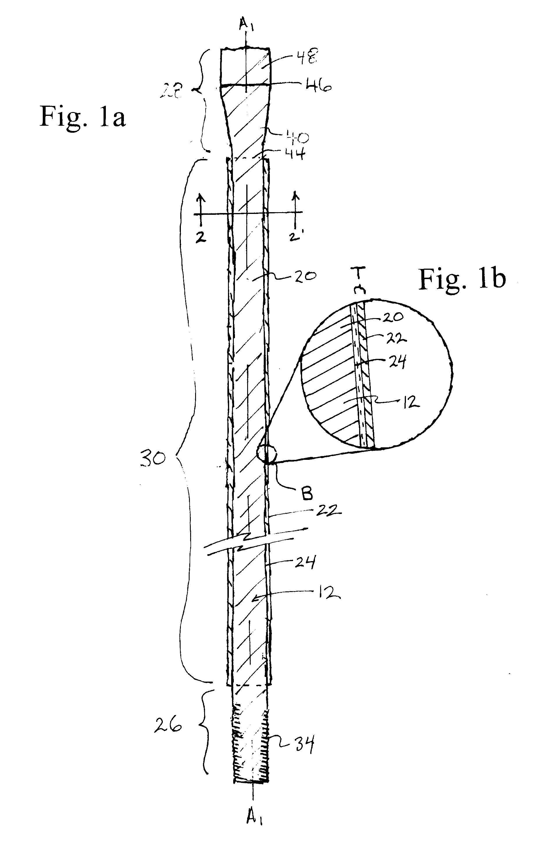
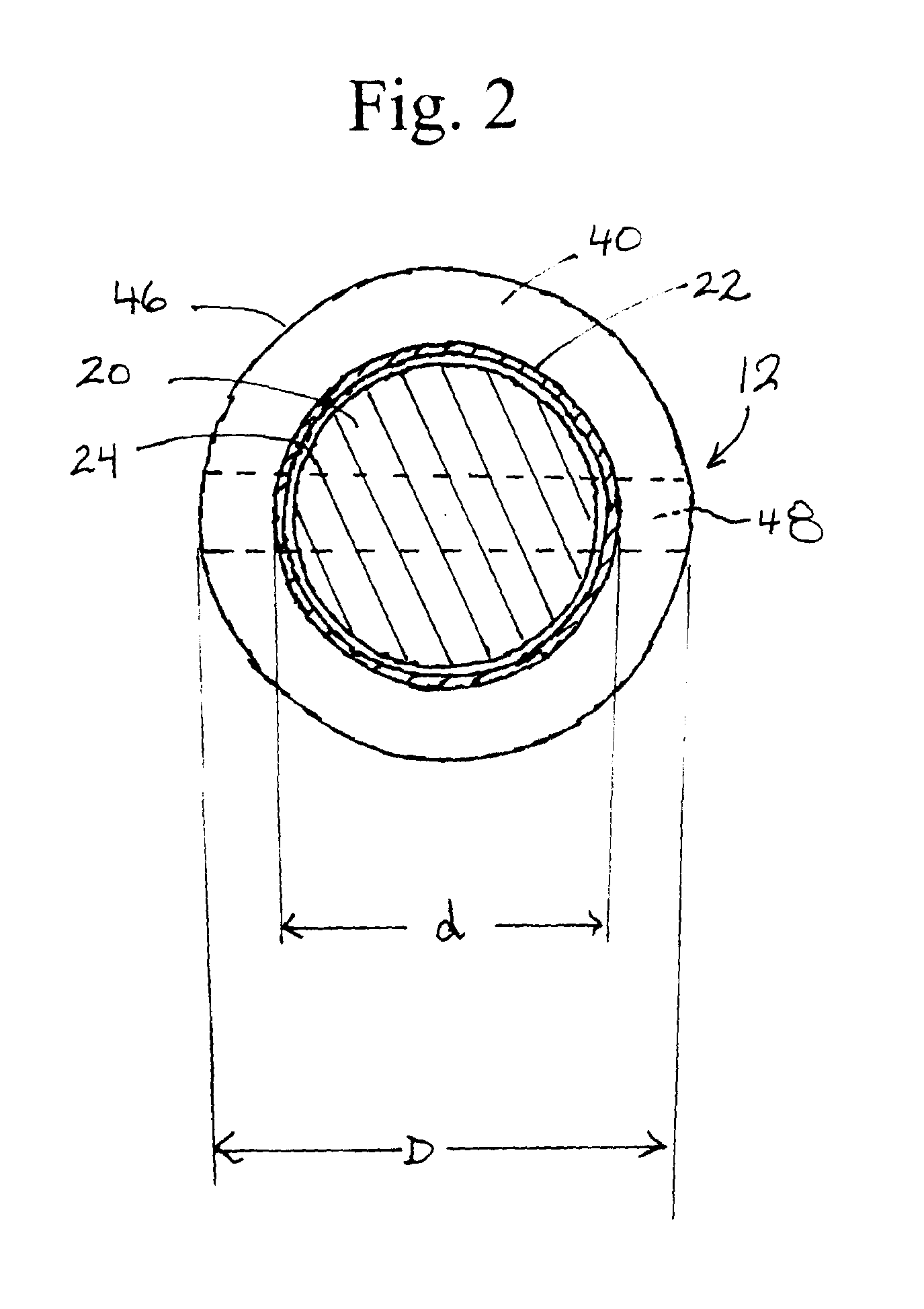
[0071]FIGS. 1a, 1b and 2 show best the cone bolt 12 used in the mine roof support system 10. The cone bolt 12 has an overa...


PUM

PropertyMeasurementUnit
radial thicknessaaaaaaaaaa

Abstract

A mine roof support assembly for anchoring in a bore hole by means of a resin, cementitious grout which includes an elongated reinforcing tendon which extends from a proximal end portion to a distal end portion. A slip sheath formed from a heat shrunk plastic, is secured by heat shrinkage radially about the tendon. The sheath is mechanically coupled to the tendon so as to allow the desired axial sliding of the tendon relative to the sheath on the application of predetermined forces which sufficient to effect any desired yielding movement of the tendon in the bore hole. An anti-bonding agent or coating and / or anticorrosive may be interposed between the sheath and the tendon, whereby the sheath substantially encapsulates and limits the admixing of the interposed anti-bonding agent / anti-corrosive coating with the resin.

Description

SCOPE OF THE INVENTION[0001]The present invention relates to a roof and wall support system, and more particularly a mine roof support system which incorporates a grout or resin anchored yieldable cone bolt, and the method of manufacturing same.BACKGROUND OF THE INVENTION[0002]In ground control systems, such as mine roof, retaining wall and rock wall support systems (hereinafter collectively generally referred to as “mine roof support systems”), threaded rod-like reinforcing bolts, rebars, tendons or anchor rods are embedded into 1 to 2.5 inch diameter bore holes which are drilled into the rock complex. The rebar, bolt or anchor rods are secured in place within the bore hole by a resin or grout. Typically, the resin used to secure the reinforcing rods consists of a two-part resin which is provided in frangible cartridges sized for insertion into the bore hole immediately ahead of the rod or is pumped prior or after the bolt is installed.[0003]Depending on the ground support type use...

Claims


Application Information

Patent Timeline
Patent Type & Authority Applications(United States)
IPC IPC(8): E21D21/00B32B38/00
CPCB29C63/42E21D21/0033E21D21/0013B29K2027/18
Inventor CAI, MINGCHAMPAIGNE, DENIS
Owner DSI UNDERGROUND CANADA LTD SOUTERRAIN DSI CANADA LTEE
Learn More