Rotor for an electric motor, an electric motor and a production process for an electric motor

Active Publication Date: 2012-01-19
HILTI AG
View PDF9 Cites 31 Cited by
  • Summary
  • Abstract
  • Description
  • Claims
  • Application Information

AI Technical Summary

Benefits of technology

[0046]It has proven to be especially preferred to have a plurality of peripheral encoding recesses that is formed with a plurality of edge recesses. The arrangement of the core lamination that takes manufacturing tolerances into account, especially in a transfer mold, is ensured in that a web of the transfer mold engages into the edge recess, thereby affixing the core lamination in the transfer mold. By stacking the plurality of core laminations on top of each other, a rotor core is created with a groove formed in the circumferential area of the rotor core by the edge recesses, said groove being held in a web of the transfer mold. Fundamentally, the arrangement of the groove and the web on the rotor core and on the transfer mold can be reversed. This is possible as long as the web does not have a detrimental effect on the rotor core or as long as it can be compensated for. According to this preferred embodiment, the core laminations can already be stacked by means of the encoding marking arrangement, within the framework of the manufacturing tolerance. A readjustment or a balancing procedure is not required; in any case, such separate correction steps are considerably reduced.
[0047]Moreover, it is preferable for a plurality of peripheral lamination points, especially holes or the like, to be formed at a distance from the edge. They can be filled with transfer-molding compound and can assist in securing a first core lamination relative to a second core lamination in a way that complies with the

Problems solved by technology

A problematic aspect of the above-mentioned types of connection is fundamentally the relatively laborious assembly.
Thus, when individual core laminations are attached in order to form the rotor core on a rotor shaft, the tolerances cannot be ascertained sufficiently precisely, which usually calls for a subsequent work step, namely, the labor-intensive balancing of the rotor.
During the balancing procedure, in particular, the placement of balancing

Method used


Image

  • Rotor for an electric motor, an electric motor and a production process for an electric motor
  • Rotor for an electric motor, an electric motor and a production process for an electric motor
  • Rotor for an electric motor, an electric motor and a production process for an electric motor

Examples


Embodiment Construction

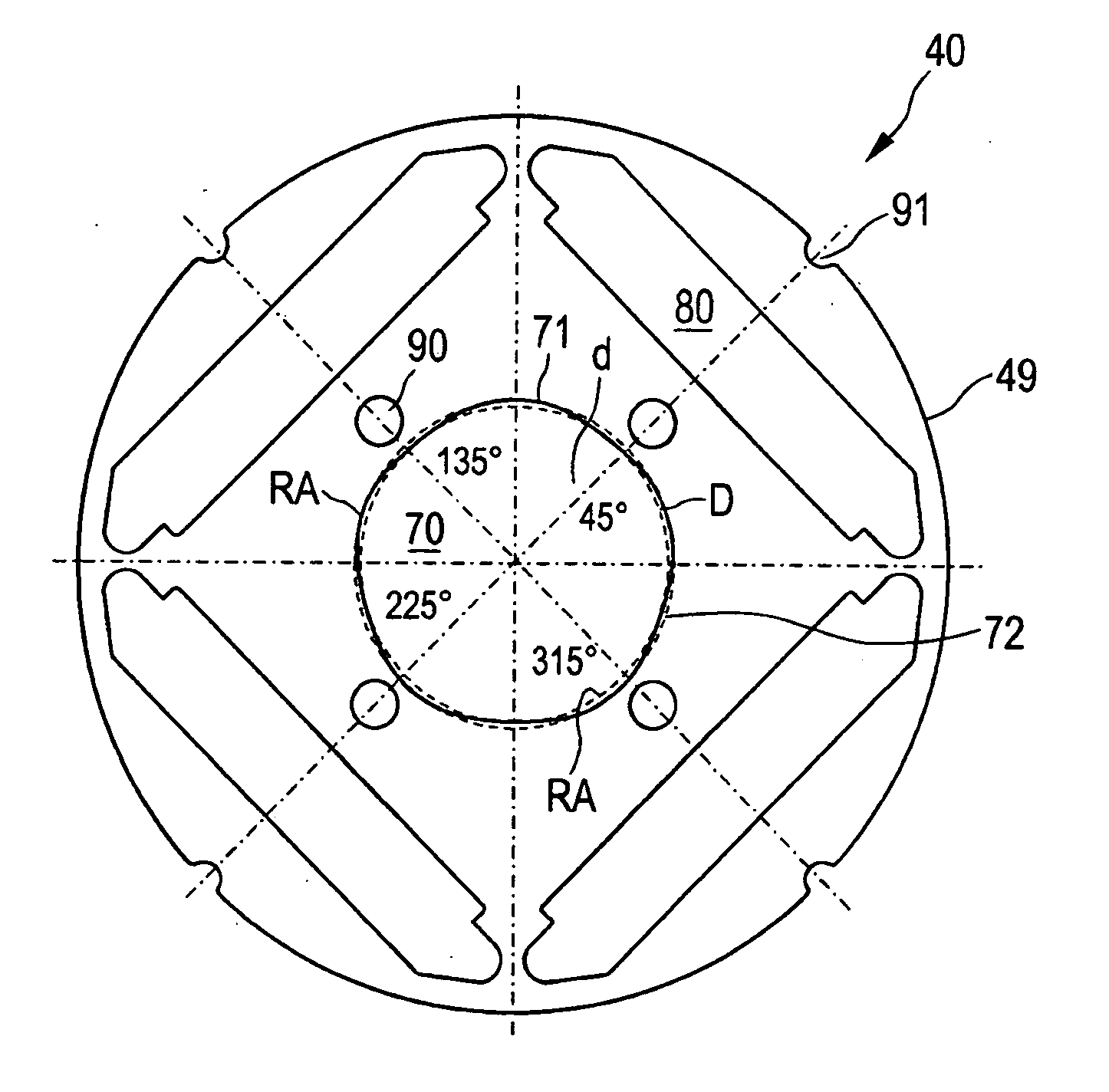
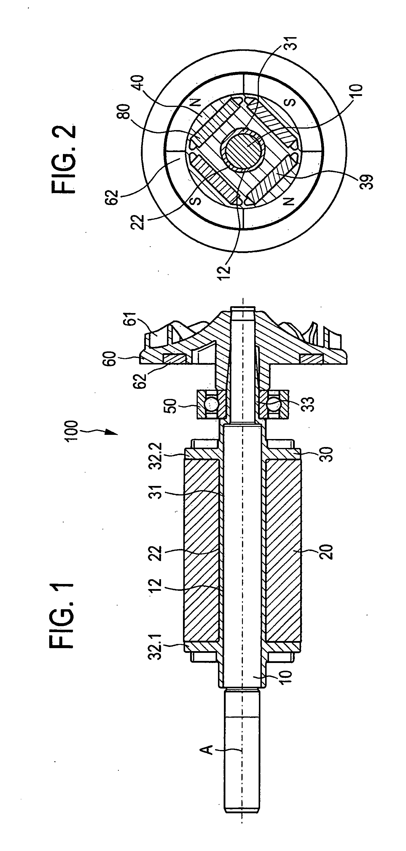
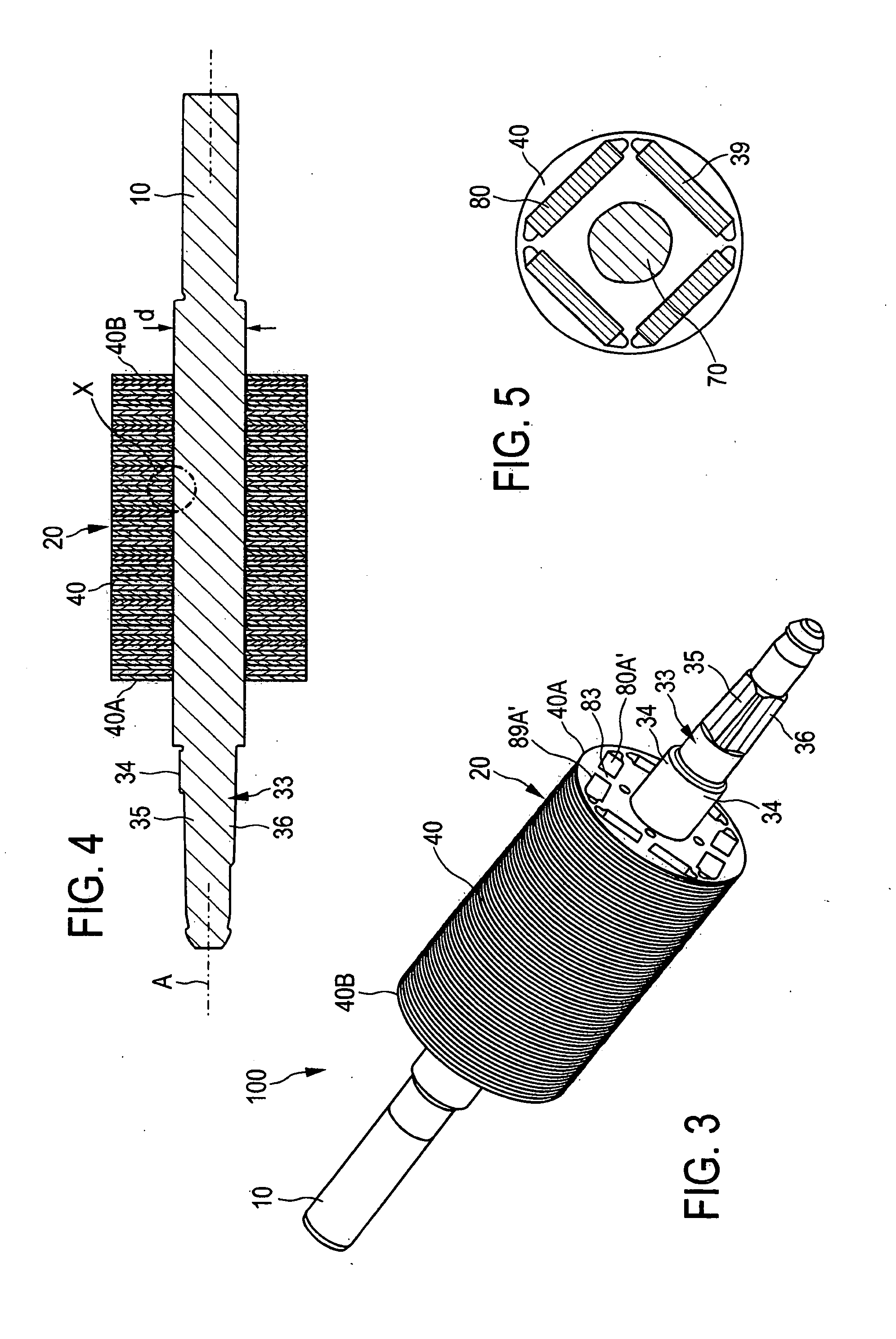
[0076]FIG. 1 shows a completely assembled rotor 100 for a permanently excited electric motor 1000, shown in greater detail in FIG. 17, which in the present case is configured as a BLDC electric motor with an arrangement consisting of a rotor 100 and a stator 200. For this purpose—as can be seen in FIG. 17—the rotor 100 is arranged so as to be rotatably and magnetically coupled in a recess of the stator 200. FIG. 1 shows the rotor 100 with a rotor shaft 10 and with a rotor core 20 that is attached onto the rotor shaft 10 and that is made up of a plurality of core laminations 40 also shown in FIGS. 2, 5 and 6. In the present case, the core laminations 40 are stacked along an axis A in order to form the rotor core 20. The recesses 80 (as the receiving structure), that are arranged at four peripheral angular positions as shown in FIG. 2, form a chamber (as the receiving element) in the stacked arrangement of the core laminations 40, each chamber receiving a permanent magnet 39 (as the p...


PUM

PropertyMeasurementUnit
Fractionaaaaaaaaaa
Fractionaaaaaaaaaa
Diameteraaaaaaaaaa

Abstract

A rotor (100) for an electric motor (1000). The rotor (100) has a rotor shaft (10) and a rotor core (20) attached onto the rotor shaft (10). The rotor core has a plurality of core laminations (40, 140) arranged along an axis (A) of the rotor core (20), and has a plurality of poles of at least one pole pair, the core lamination (40, 140) having: a central recess (70, 170) through which the rotor shaft (10) passes and which has a contour (71, 171) as well as adjacent areas (AF), and a plurality of receiving structures arranged at peripheral angular positions in order to each form a receiving element for a pole-forming element on the rotor core (20). In this context, it is provided according to the invention that the rotor core has a surface (OF) facing the rotor shaft (10) that is formed together with the adjacent areas (AF) of the central recess (70, 170) of the plurality of core laminations (40, 140), and that has uneven areas crosswise to the axis (A) of the rotor core (20) that are formed by the contours (71, 171) of the central recesses (70) of the plurality of core laminations (40, 140). The contours (71, 171) of the central recesses (70, 170) of at least a first core lamination and a second core lamination of the plurality of core laminations (40, 140) are arranged so as not to be congruent with each other.

Description

[0001]This claims the benefit of German Patent Application DE 10 2010 031 399.8, filed Jul. 15, 2011 and hereby incorporated by reference herein.[0002]The invention relates to a rotor for an electric motor, especially for a permanently excited electric motor. The invention also relates to a production process for a rotor or for an electric motor.BACKGROUND[0003]A rotor of the above-mentioned type for a permanently excited electric motor is known, for example, from Japanese patent JP 2005 012859. It is a known procedure to use various adhesion, welding or laminating techniques to affix a rotor core to a rotor shaft, or to arrange core laminations of the rotor core on each other. In Japanese patent 2002 354722, a rotor core is connected to the rotor shaft by means of a plastic transfer-molding process. It is also a known procedure to compression-mold a rotor core onto a smooth or knurled rotor shaft.[0004]In a permanently excited electric motor such as, for example, a BLDC or BLAC ele...

Claims


Application Information

Patent Timeline
IPC IPC(8): H02K1/28F04B17/00H02K15/02H02K1/27
CPCH02K1/276H02K1/30Y10T29/49012H02K15/03H02K15/12H02K15/02
Inventor RIEDL, REINHARDERHARDT, JOCHEN
Owner HILTI AG
Why Eureka
Try Eureka