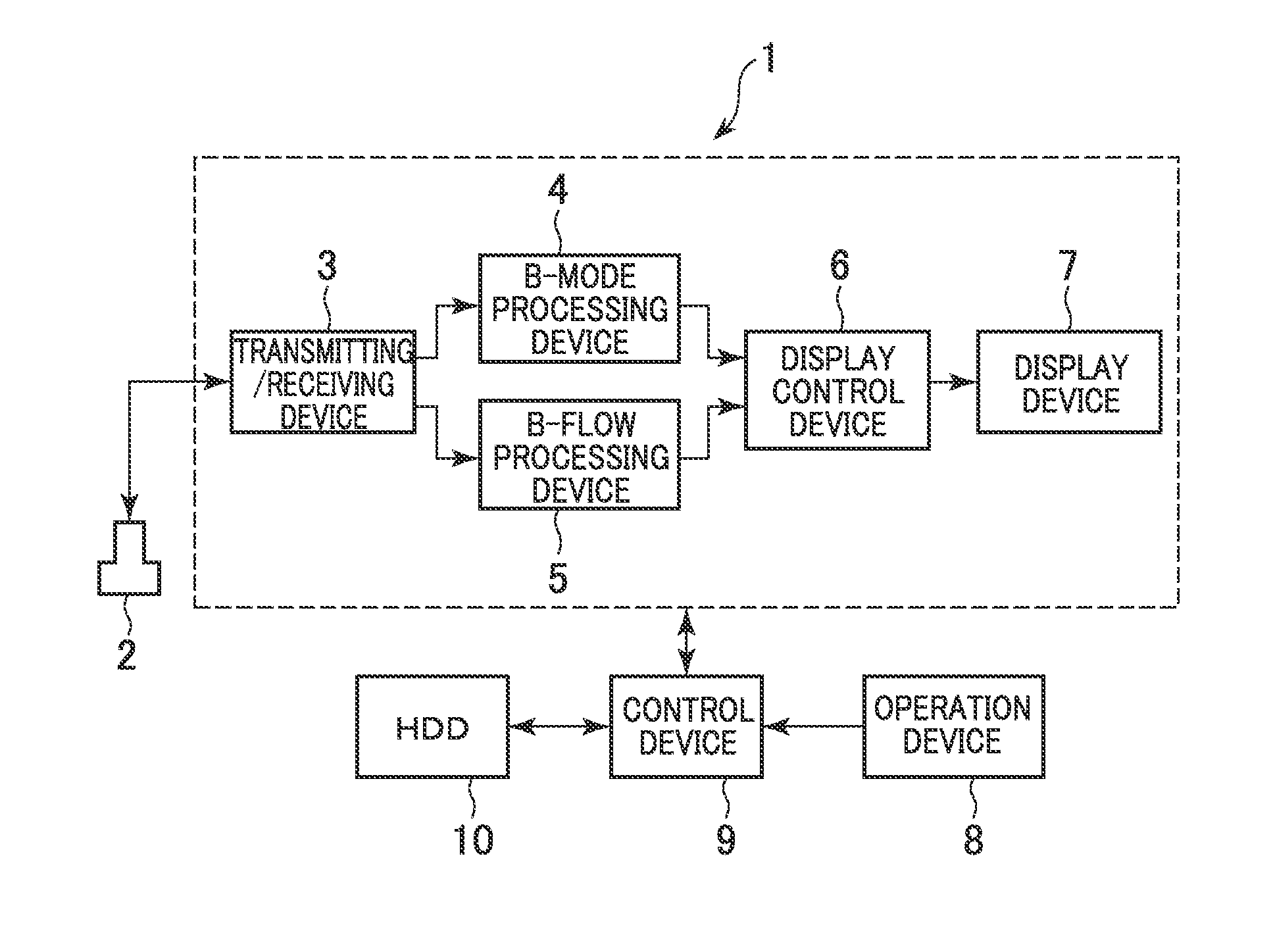
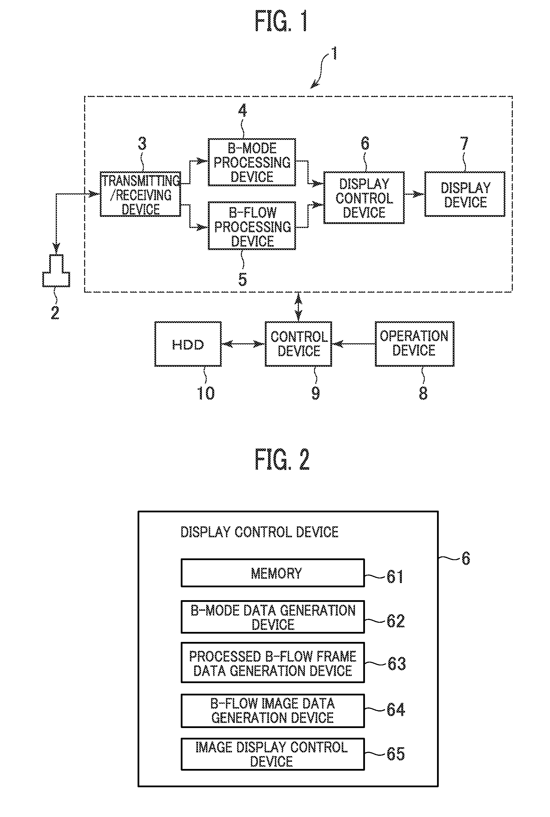
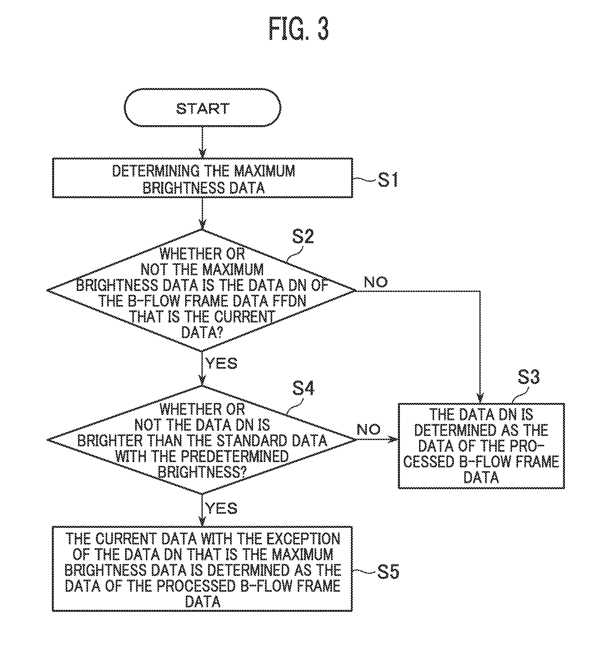
Ultrasound diagnostic apparatus

a diagnostic apparatus and ultrasonic technology, applied in the field of ultrasonic diagnostic apparatus, can solve the problems of difficult to see images, difficult to see in color doppler image and power doppler, etc., and achieve the effects of high blood flow power, high brightness, and fast blood speed

Active Publication Date: 2012-01-19
GE MEDICAL SYST GLOBAL TECH CO LLC
View PDF7 Cites 2 Cited by
  • Summary
  • Abstract
  • Description
  • Claims
  • Application Information

AI Technical Summary

Benefits of technology

[0027]According to the above-mentioned aspects, by displaying the blood flow image based on the processed frame data with the exception of the error data of pixel data corresponding each other in the plurality of frame data, display of images momentarily showing high

Problems solved by technology

Such images are difficult to be seen when frames have momentary high brightness in the blood flow image.
Further, it is also difficult to b

Method used


Image

  • Ultrasound diagnostic apparatus
  • Ultrasound diagnostic apparatus
  • Ultrasound diagnostic apparatus

Examples


second embodiment

[0093]Next, a second embodiment is explained. Only configuration and operation different from the first embodiment are explained below.

[0094]In this embodiment, the processed B-flow frame data generation device 63 generates the processed B-flow frame data FFD for each frame using data that the brightness is the central data of the pixel data corresponding each other in a plurality of B-flow frame data ffd at different time phases.

[0095]For the generation of the processed B-flow frame data FFD in the present embodiment is explained based on the flow chart in FIG. 13. Here, B-flow frame data ffdn, ffd (n-1), ffd (n-2) of the frame Fn, F (n-1), F (n-2) are objects for processing of steps S21 and S22 in FIG. 13, and display on the frame Fn is explained.

[0096]First in step S21, the processed B-flow frame data generation device 63 determines the data have a brightness that is the median of the pixel data corresponding to each other in the B-flow frame data ffdn, ffd (n-1), ffd (n-2). For ...


PUM


Abstract

An ultrasonic diagnosis apparatus includes a frame data generation device configured to generate a frame data of a blood flow image based on echo signals obtained by transmissions and receptions of ultrasonic waves on a same acoustic ray, a processed frame data generation device configured to generate a processed frame data using current data excluding an error data having a higher brightness, a faster blood speed, or a higher blood flow power than a brightness, a blood speed, or a blood flow power of standard data within pixel data corresponding to each other in a plurality of frame data at different time phases, and an image display control device configured to display a blood flow image based on the processed framed data.

Description

CROSS REFERENCE TO RELATED APPLICATIONS[0001]This application claims the benefit of Japanese Patent Application No. 2010-159470 filed Jul. 14, 2010, which is hereby incorporated by reference in its entirety.BACKGROUND OF THE INVENTION[0002]The embodiments described herein relate to an ultrasonic diagnostic apparatus for displaying a blood flow image.[0003]For blood flow images, a B-flow image, a color Doppler image, and a power Doppler image are listed for example. Those blood flow images are generated based on echo signals obtained from multiple transmitting / receiving of ultrasonic waves on the same acoustic ray.[0004]For example, brightness of moving objects is displayed higher in the B-flow image so that a high bright image momentarily may be displayed if a subject moves while the ultrasonic waves transmit / receive or an ultrasonic probe moves. Also, in the B-flow image close to a heart, as tissues around the heart move, there may be frames in that such parts are shown with high b...

Claims


Application Information

Patent Timeline
IPC IPC(8): A61B8/06
CPCA61B8/06A61B8/5269A61B8/13A61B8/14G16Z99/00
Inventor MIYAMA, KOJI
Owner GE MEDICAL SYST GLOBAL TECH CO LLC
Why Eureka
Try Eureka