
Dynamic Inter-Spinous Process Spacer

Active Publication Date: 2012-01-19
AFLATOON KAMRAN
View PDF6 Cites 12 Cited by
  • Summary
  • Abstract
  • Description
  • Claims
  • Application Information

AI Technical Summary

Benefits of technology

[0010]Accordingly, there is provided an interspinous process spacer and method of implantation for distraction of the vertebra including an expandable member, a self sealing percutaneous access port in fluid engagement with the expandable member and an anchor member secured to and in fluid engagement with said tubular member. The anchor member may be an arcuate channel mechanically secured to adjacent spinous process by bone screws through a plurality of slots in the legs of the channel. The port allows for adding or removing fluid from the one or more chambers or envelopes of the expandable member in order to adjust the volume of the expandable member and thus the interspinous process spacing. Subsequent to initial implantation and expansion the volume of the expanda

Problems solved by technology

Degeneration of the intervertebral discs and the concomitant instability and translocation of the vertebra (spondylolisthesis) is a common cause of back pain and may result from a variety of problems including congenital deformity, age related degeneration, osteoporosis, tumor and disc herniation as a result of trauma.
Disc degeneration, for whatever reason, results in compression of the spinal nerve roots (stenosis) resulting in pain.
However, many patients suffering from degenerative conditions have comorbidities that make them less than perfect surgical candidates.
The potential complications of IPD include dislodgement of the spacer, incorrect positioning or sizing of the spacer, fracture of the spinous process, foreign body reaction to the spacer (e.g., allergic reaction to titanium alloy) and mechanical failure of the spacer.

Method used


Image

  • Dynamic Inter-Spinous Process Spacer
  • Dynamic Inter-Spinous Process Spacer
  • Dynamic Inter-Spinous Process Spacer

Examples


Embodiment Construction

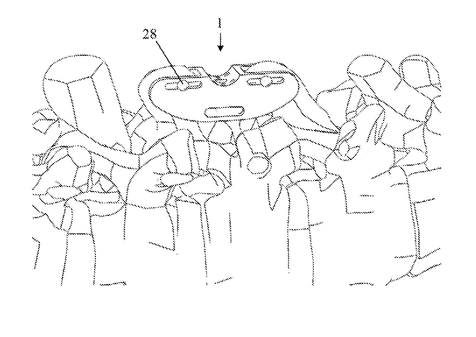
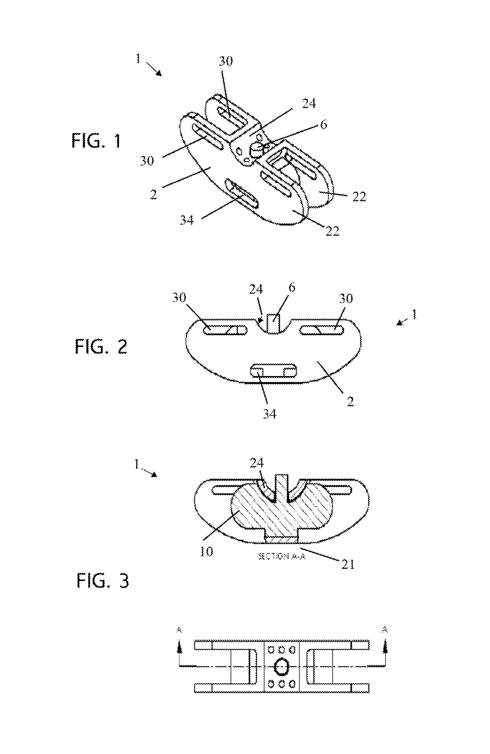
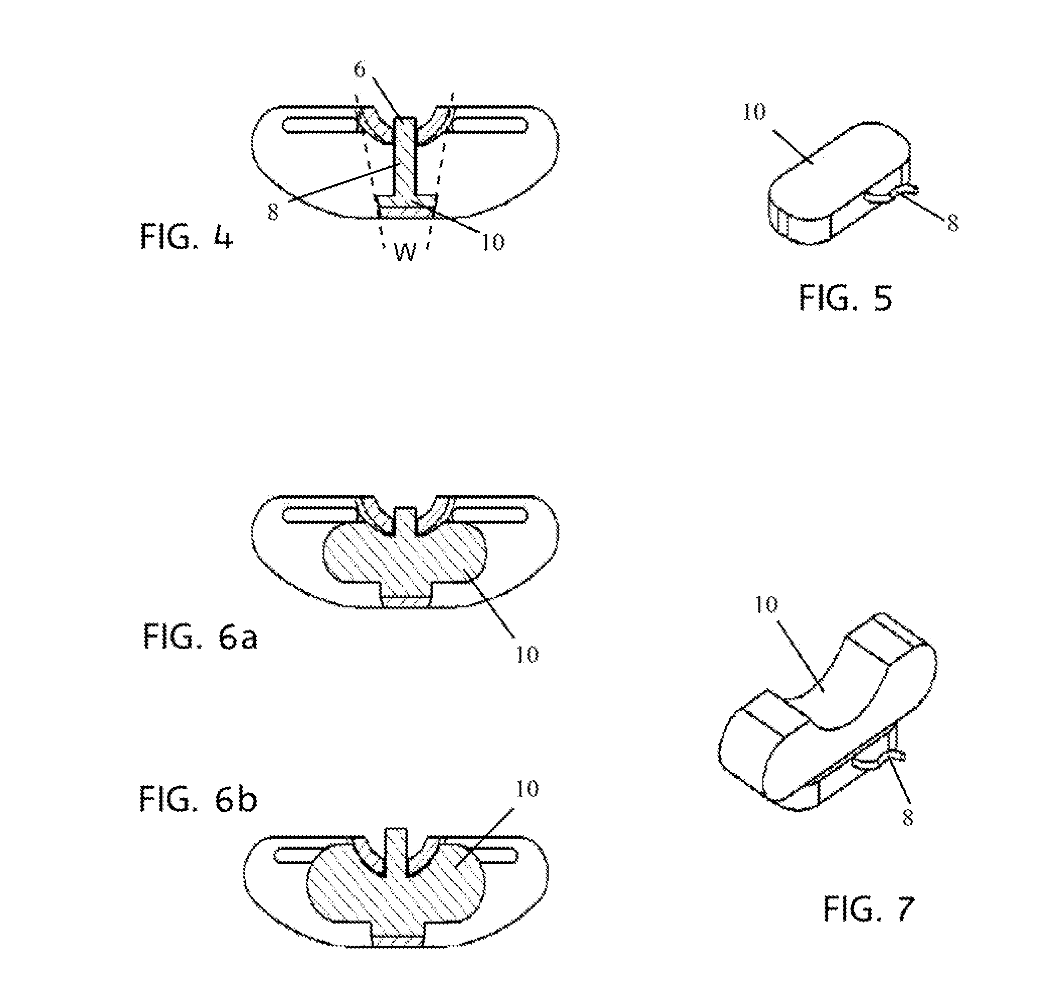
[0029]With collective reference to FIGS. 1 through 8, an interspinous process spacer 1 having an anchor member 2 is provided. In the depicted, preferred embodiment the anchor member 2 has a generally C-channel cross section have opposing legs (or flanges) 22 of preferably equal length extending from a base member (or web) 24. The legs 22 are preferably orthogonal to the base member 24 but may be splayed outward slightly from the depicted 90° angle to accommodate vertebral physiology of the spinous processes in certain regions of the human (or other) spine. The term “orthogonal” as used herein is inclusive of such splayed angles (i.e. non-90° angles). The legs 22 are preferably splayed not more than 15° each on either side so as to maintain sufficient contact with the bone while not interfering with adjacent tissue structures and are preferably splayed from 5° to 15° and even more preferably 5° to 10°. Some resilience in the leg construction may also be provided and desirable to furt...


PUM


Abstract

An interspinous process spacer and method of implantation for distraction of the vertebra including an expandable member, a self sealing percutaneous access port in fluid engagement with the expandable member and an anchor member secured to and in fluid engagement with said tubular member. The anchor member may be an arcuate channel mechanically secured to adjacent spinous process by bone screws through a plurality of slots in the legs of the channel. The port allows for adding or removing fluid from the one or more chambers or envelopes of the expandable member in order to adjust the volume of the expandable member and thus the interspinous process spacing. Subsequent to initial implantation and expansion the volume of the expandable member may be increased or decreased in a non-surgical in-office procedure in which a needle is used to add or remove fluid from the expandable member via the port and tubular member. The flowable material / fluid may be a liquid such as saline, gel such as silicone, or a viscous polymer and my further remain in a liquid state or harden to a viscoelastic state with or without additional intervention.

Description

CROSS-REFERENCE TO RELATED APPLICATIONS[0001]The present application claims priority to U.S. provisional patent application Ser. No. 61 / 364,473 filed Jul. 15, 2010 which is incorporated herein by reference.BACKGROUND OF THE INVENTION[0002]1. Field of the Invention[0003]The present invention relates generally to devices and methods for treating spinal disorders and more specifically to a variable volume inter-spinous process spacer that can be implanted in a minimally invasive manner.[0004]2. Description of the Background[0005]Degeneration of the intervertebral discs and the concomitant instability and translocation of the vertebra (spondylolisthesis) is a common cause of back pain and may result from a variety of problems including congenital deformity, age related degeneration, osteoporosis, tumor and disc herniation as a result of trauma. Disc degeneration, for whatever reason, results in compression of the spinal nerve roots (stenosis) resulting in pain. Other causes of stenosis ...

Claims


Application Information

Patent Timeline
IPC IPC(8): A61B17/70A61B17/88
CPCA61B17/7065A61B17/7067A61B2017/00557
Inventor AFLATOON, KAMRAN
Owner AFLATOON KAMRAN
Learn More