Method and apparatus for directional drilling

a directional drilling and method technology, applied in the direction of directional drilling, survey, borehole/well accessories, etc., can solve the problems of stalling the drill motor, changing the tool face, and the method of directional drilling, so as to achieve the effect of sacrificing the directional control of the drill tool fa

Active Publication Date: 2012-01-26
RUGGED ENG DESIGNS
View PDF4 Cites 33 Cited by
  • Summary
  • Abstract
  • Description
  • Claims
  • Application Information

AI Technical Summary

Benefits of technology

[0007]It is therefore an object of the invention to provide a method and apparatus for directional drilling that permits the drill string to be rotated without sacrificing directional control of the drill tool face.

Problems solved by technology

However, this method of directional drilling has certain disadvantages.
For example: during directional drilling the sliding drill string has a tendency to “stick-slip”, especially in bores that include more than one nonlinear bore segment or in bores with a long horizontal bore segment; when the drill string sticks the drill bit may not engage the drill face with enough force to advance the bore, and when the friction is overcome and the drill string slips the drill bit may be forced against the bottom of the bore with enough force to damage the bit, stall the drill motor, or drastically change the tool face, each of which is quite undesirable; and, rotation of the drill string helps to propel drill cuttings out of the bore, so when the drill string rotation is stopped drill cuttings can accumulate and create an obstruction to the return flow of drill mud, which is essential for the drilling operation.
Furthermore, during directional drilling the reactive torque causes the stationary drill string to “wind up”, which can also drastically change the tool face.

Method used


Image

  • Method and apparatus for directional drilling
  • Method and apparatus for directional drilling
  • Method and apparatus for directional drilling

Examples


Embodiment Construction

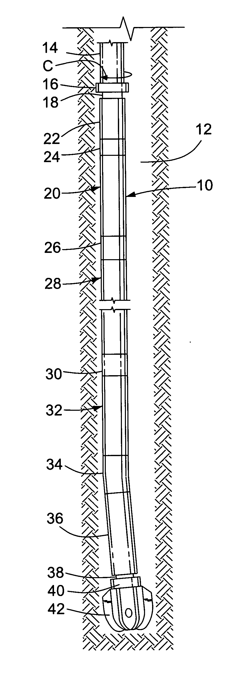
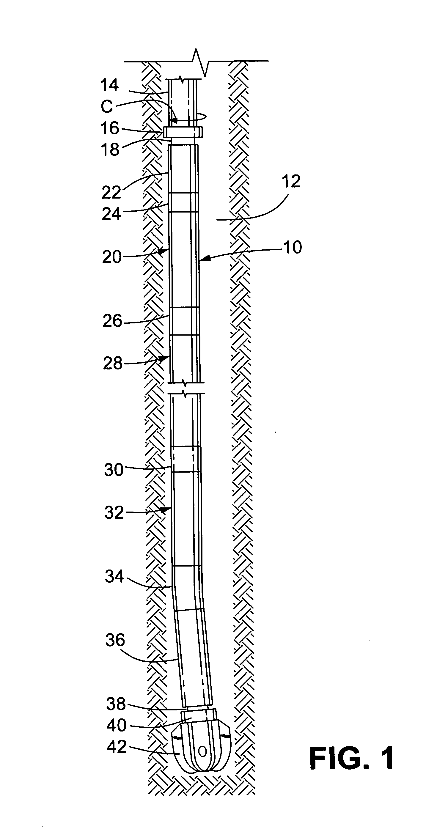
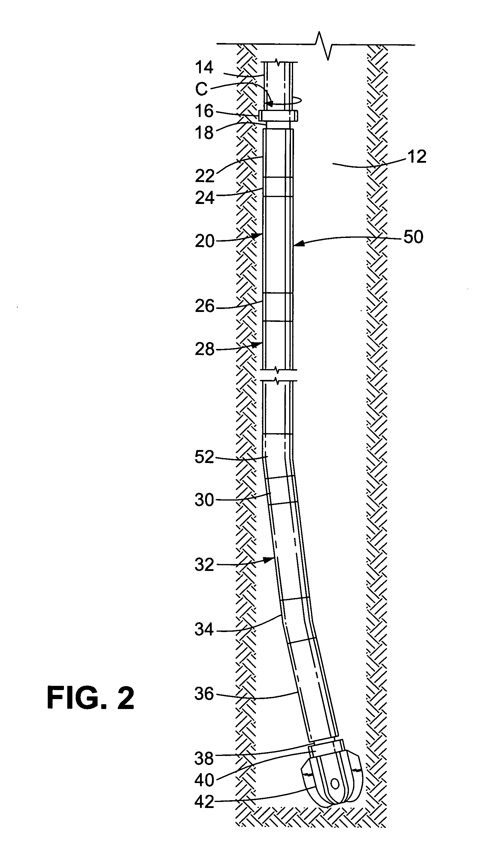
[0021]The invention provides a bottom-hole assembly (BHA) for directional drilling of subterranean bore holes. The BHA includes a torque generator with a drive shaft at its top end. The drive shaft is connected to a bottom end of a drill string. A housing of the torque generator is connected to a bearing assembly that surrounds the drive shaft and permits the BHA to rotate with respect to the drill string independently of the drive shaft. A measurement while drilling (MWD) unit, a bent sub, and a mud motor that turns a drill bit are rigidly connected to a bottom end of the torque generator housing. Rotation of the drill string rotates the drive shaft, which induces the torque generator to generate a torque that counters a reactive torque generated by the mud motor as it turns the drill bit against a bottom of the bore hole. By controlling the rotational speed of the drill string, the bottom-hole assembly can be controlled to drill straight ahead, i.e. a linear bore segment, or direc...


PUM


Abstract

A bottom-hole assembly for directional drilling incorporates a torque generator with a drive shaft connected to a drill string. The torque generator generates a torque that counters a reactive torque when a drill bit of the bottom-hole assembly is driven. When the drill string is rotated at a static drive speed, a drill tool face of the bottom-hole assembly is stabilized to drill a nonlinear bore segment. When the drill string is rotated at a rotational speed other than the static drive speed the bottom-hole assembly is rotated to drill a linear bore segment.

Description

RELATED APPLICATIONS[0001]This is the first application filed for this invention.FIELD OF THE INVENTION[0002]This invention relates in general to drilling equipment used to drill subterranean bore holes and, in particular, to a method and apparatus for directional drilling in which a bottom-hole assembly is operated to drill both linear and nonlinear segments of a borehole.BACKGROUND OF THE INVENTION[0003]Directional drilling is well known in the art and commonly practiced. Directional drilling is generally practiced using a bottom-hole assembly connected to a drill string that is rotated at the surface using a rotary table or a top drive unit, each of which is well known in the art. The bottom-hole assembly generally includes a positive displacement drill motor that drives a drill bit via a “bent” housing that has at least one axial offset of around 4 degrees. A measurement-while-drilling (MWD) tool connected to a top of the drill motor provides “tool face” information to tracking ...

Claims


Application Information

Patent Timeline
Patent Type & Authority Applications(United States)
IPC IPC(8): E21B7/08E21B7/06E21B44/00E21B7/04
CPCE21B4/02E21B43/126E21B7/068E21B7/04
Inventor ROSENHAUCH, IRWIN
Owner RUGGED ENG DESIGNS
Why Eureka
Try Eureka