Touch sensing device

a sensing device and touch technology, applied in the field of touch sensing devices, can solve the problems of inability to expand pitch indefinitely, inability to precisely and inability to accurately detect the coordinates of the touch location

Active Publication Date: 2012-01-26
AU OPTRONICS CORP
View PDF3 Cites 40 Cited by
  • Summary
  • Abstract
  • Description
  • Claims
  • Application Information

AI Technical Summary

Benefits of technology

[0018]In one embodiment, each of the first sensing pads is of a polygon with more than four sides, and each of the second sensing pads is of a polygon with more than four sides.
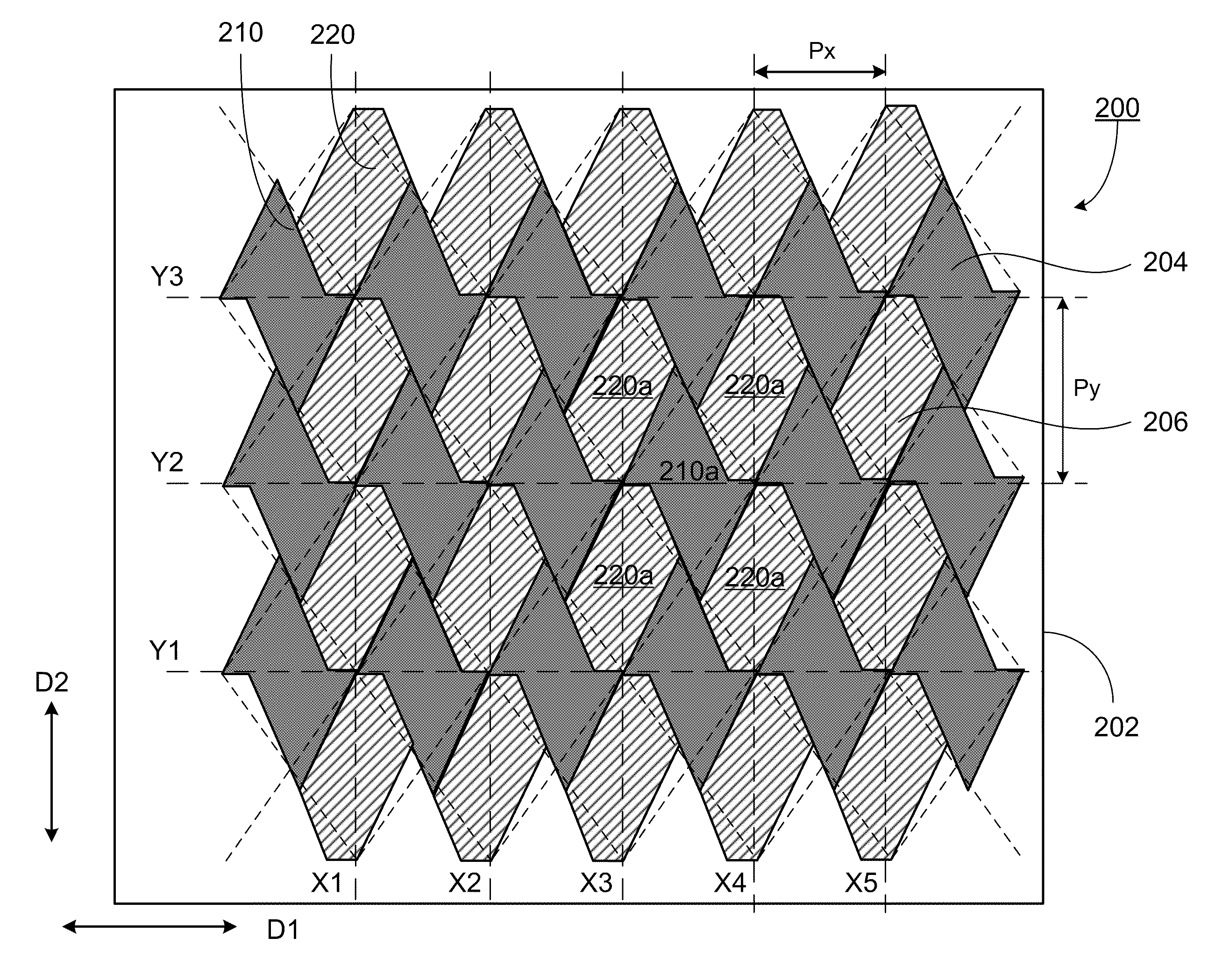
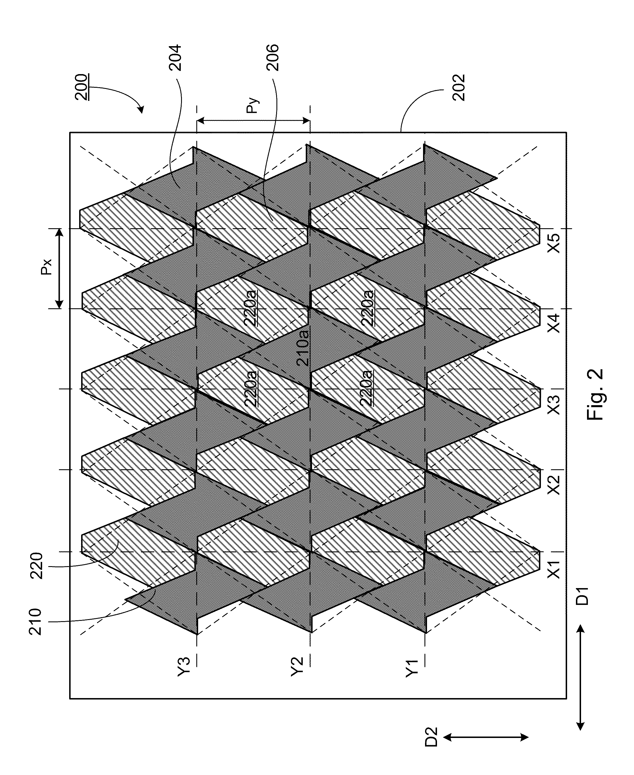
[0019]In one embodiment, each of the first sensing pads is a hexagon with two isosceles triangles oriented such that the vertex of one isosceles triangle is opposite to the vertex of the other isosceles triangle, and the base sides of the two isosceles triangles are partially overlapped so that the hexagon has four long sides with an equal first length, L1, and two short sides with an equal second length, L2<L1, and each side parallel to its corresponding opposite side, wherein each short side defines an angle, α, relative to two adjacent long sides, respectively. Each of the second sensing pads is a hexagon having two longest sides with an equal first length, J1, and two shortest sides with an equal second length, J2<J1, and each side parallel to its corresponding opposite side, wherein each shortest side defines an angle, β, relative to two adjacent sides, respectively, wherein the angles α and β are complementary to each other, J1=L2 and J2=L2. The first sensing pads and the second sensing pads are disposed along the first direction and the second direction, respectively, such that each of the first sensing pads and the corresponding second sensing pads are entangled each other along with the second direction, and each of the first sensing pads is surrounded by four second sensing pads and vice versus. Each short side of the first sensing pad is closest to and faces one shortest side of the second sensing pad correspondingly.

Problems solved by technology

However, its linearity is not very accurate.
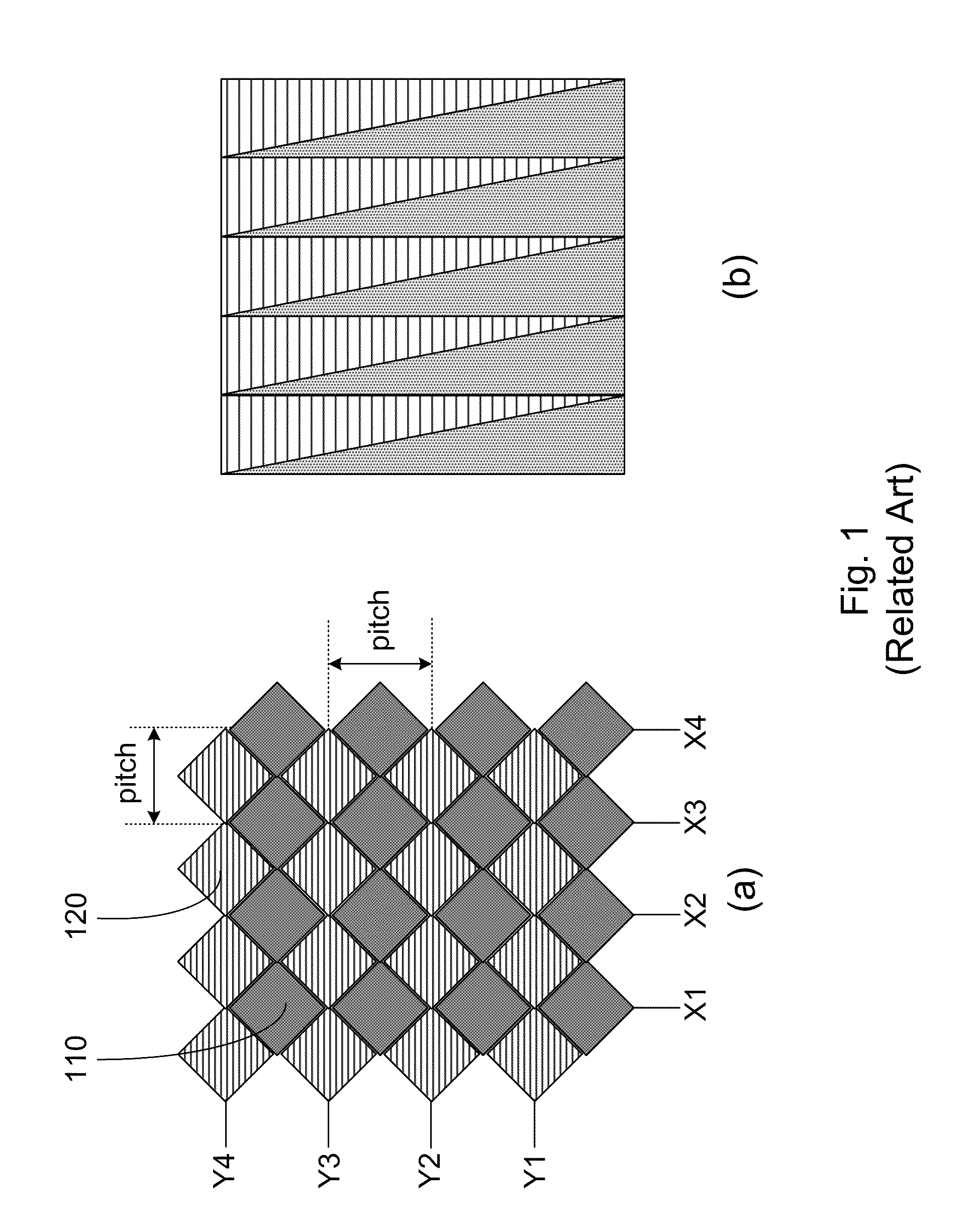
However, the pitch cannot be enlarged indefinitely, since the limitation of the figure size.
If the pitch is too large, the finger cannot simultaneously touch two or more sensing units to induce an effective capacity, thereby not being able precisely to detect the coordinates of the touch location by utilizing the variation of the capacity of the two or more sensing units.
On the other hand, since the channels supported by an IC are also limited, the number of the sensing units cannot be increased unlimitedly.
If the size is larger than 12 inches, the touch detection has a poor linearity, and touch panel can not be utilized for precisely detecting the coordinates.
Therefore, a heretofore unaddressed need exists in the art to address the aforementioned deficiencies and inadequacies.

Method used


Image

  • Touch sensing device
  • Touch sensing device
  • Touch sensing device

Examples


Embodiment Construction

[0032]The present invention is more particularly described in the following examples that are intended as illustrative only since numerous modifications and variations therein will be apparent to those skilled in the art. Various embodiments of the invention are now described in detail. Referring to the drawings, like numbers indicate like components throughout the views. As used in the description herein and throughout the claims that follow, the meaning of “a”, “an”, and “the” includes plural reference unless the context clearly dictates otherwise. Also, as used in the description herein and throughout the claims that follow, the meaning of “in” includes “in” and “on” unless the context clearly dictates otherwise.

[0033]The terms used in this specification generally have their ordinary meanings in the art, within the context of the invention, and in the specific context where each term is used. Certain terms that are used to describe the invention are discussed below, or elsewhere ...


PUM


Abstract

The present invention relates to a touch sensing device. In one embodiment, the touch sensing device includes a plurality of first touch electrodes and a plurality of second touch electrodes, alternately arranged along a first direction and a second direction substantially perpendicular to the first direction to form a sensing matrix, such that each first touch electrode and a corresponding second touch electrode are entangled each other along with at least one of the first and second directions.

Description

FIELD OF THE INVENTION[0001]The present invention relates generally to a touch sensing device, and more particularly to touch sensor designs of a touch sensing device.BACKGROUND OF THE INVENTION[0002]Touch sensing technology capable of providing a natural interface between an electronic system and user has found widespread applications in a variety of fields, for example, in mobile phones, personal digital assistants (PDAs), automatic teller machines (ATMs), game machines, medical devices, liquid crystal display (LCD) devices, light emitting diode (LED) devices, plasma display panel (PDP) devices, computing devices, and the like, where a user may input desired information and / or operate the electronic system through a touch sensing device associated with the electronic system. A touch sensing device typically includes a controller, a sensing circuit having a plurality of touch sensors and a network of control lines electrically connecting the plurality of touch sensors to the contro...

Claims


Application Information

Patent Timeline
Patent Type & Authority Applications(United States)
IPC IPC(8): G06F3/041
CPCG06F3/044G06F3/0445G06F3/0446G06F3/0448
Inventor HUANG, KUNG-CHIEHCHOU, SHIH-POLEE, SEOK LYUL
Owner AU OPTRONICS CORP
Why Eureka
Try Eureka