Ophthalmic apparatus, control method for the same, and storage medium

a technology of ophthalmic apparatus and control method, which is applied in the field of ophthalmic apparatus, a control method of the same, and a storage medium, can solve the problems of difficult influence, imposing a very heavy load on the adjustment of the apparatus, and the inability to achieve maximum light reception efficiency

Inactive Publication Date: 2012-01-26
CANON KK
View PDF6 Cites 30 Cited by
  • Summary
  • Abstract
  • Description
  • Claims
  • Application Information

AI Technical Summary

Benefits of technology

[0011]According to the first aspect of the present invention, there is provided an ophthalmic apparatus comprising: aberration correction unit arranged to correct aberration of at least one of irradiating light directed to an eye to be examined and return light from the eye; light-receiving unit arranged to receive, as return light from the eye, the light whose aberration is corrected by the aberration correction unit and then which irradiates the eye; measurement unit arranged to measure the aberration of the return light; and control unit arranged to control the aberration correction unit based on a measurement result obtained by the measurement unit and a light reception result obtained by the light-receiving unit.

Problems solved by technology

Even if, however, the aberration measured by the wavefront sensor becomes minimum, the light reception efficiency may not become maximum depending on the influences of measurement errors in the wavefront sensor due to the influence of stray light, aberration existing in the optical system of the light-receiving unit such as a collimator, and disturbance in the conjugate relation between the wavefront sensor and the light-receiving unit.
However, it is very difficult to cope with the influence of stray light to the wavefront sensor because it is difficult to predict it in advance.
This imposes a very heavy load in terms of apparatus adjustment.

Method used


Image

  • Ophthalmic apparatus, control method for the same, and storage medium
  • Ophthalmic apparatus, control method for the same, and storage medium
  • Ophthalmic apparatus, control method for the same, and storage medium

Examples


first embodiment

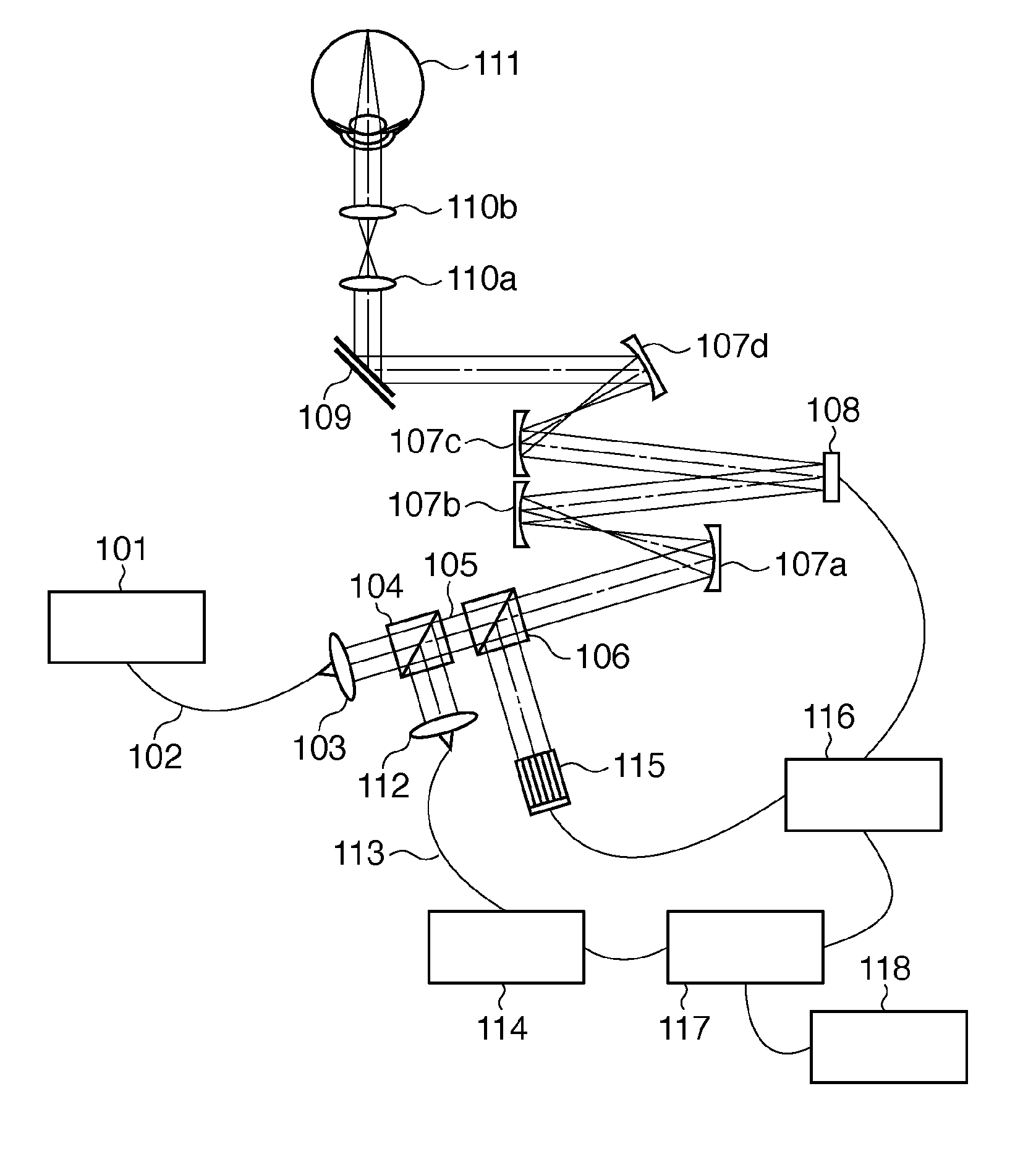
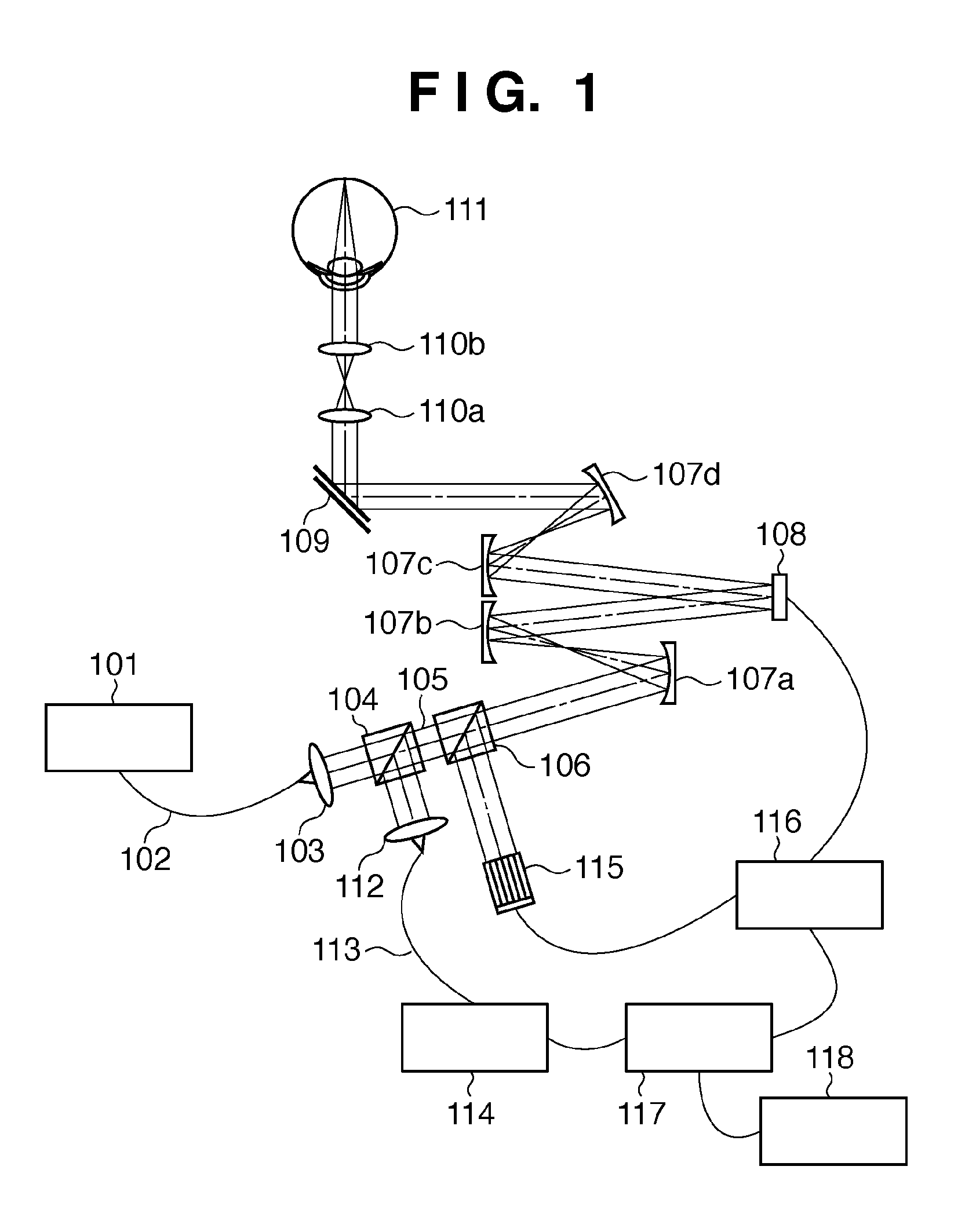
[0030]An embodiment of the present invention will be described in detail below with reference to the accompanying drawings. An example of a fundus imaging apparatus according to the present invention will be described first with reference to FIG. 1. The following is an example of a scanning laser ophthalmoscope (SLO) with an adaptive optical function.

[0031]The light source 101 is an SLD (Super Luminescent Diode) light source with a wavelength of 840 nm. The wavelength of the light source 101 for fundus imaging is preferably about 800 nm to 1,500 nm to reduce glare for an object to be examined and maintain a high resolution. Although this embodiment uses an SLD light source, it is possible to use a laser or the like. In addition, the embodiment uses the single light source for fundus imaging and wavefront measurement. However, it is possible to use different light sources for the respective operations or perform optical multiplexing on the way.

[0032]A collimator 103 collimates light ...

second embodiment

[0060]Another example of processing to be performed when the present invention is applied to scanning laser ophthalmoscope (SLO) will be described next.

[0061]The arrangement of the apparatus according to the second embodiment is the same as that in the first embodiment, which is shown in the schematic view of FIG. 1. A control procedure according to this embodiment will be described with reference to the flowchart of FIG. 7. The second embodiment is configured to implement an optimal corrected state by performing control in accordance with the maximum received light intensity obtained in the process of aberration correction instead of determining a threshold for received light intensity in advance in the manner described in the first embodiment.

[0062]First of all, in step S701, this apparatus performs control so as to minimize the aberration measured by a wavefront sensor 115 upon setting the target aberration for aberration correction to 0. This embodiment performs aberration corre...

third embodiment

[0077]The following is an example of applying the present invention to optical coherent tomography (OCT).

[0078]An example of a fundus imaging apparatus will be described with reference to FIG. 8. A light source 101 is an SLD light source with a wavelength of 840 nm. The light source 101 may be a low-coherence SLD with a wavelength width of 30 nm or more. Alternatively, the light source 101 may be an ultrashort pulse laser such as a titanium-sapphire laser.

[0079]The light emitted from the light source 101 is guided to a fiber coupler 148 through a single-mode optical fiber 102. The fiber coupler 148 splits the light emitted from the light source 101 into a light beam to a measurement light path 149 and a light beam to a reference light path 150. This apparatus is configured to use a fiber coupler with a branching ratio of 10:90 to guide 10% of the amount of incident light to the measurement light path 149, and 90% of the amount of incident light to the reference light path 150. A col...


PUM


Abstract

An ophthalmic apparatus comprises: aberration correction unit arranged to correct aberration of at least one of irradiating light directed to an eye to be examined and return light from the eye; light-receiving unit arranged to receive, as return light from the eye, the light whose aberration is corrected by the aberration correction unit and then which irradiates the eye; measurement unit arranged to measure the aberration of the return light; and control unit arranged to control the aberration correction unit based on a measurement result obtained by the measurement unit and a light reception result obtained by the light-receiving unit.

Description

BACKGROUND OF THE INVENTION[0001]1. Field of the Invention[0002]The present invention relates to an ophthalmic apparatus, a control method for the apparatus, and a storage medium and, more particularly, to an ophthalmic apparatus which has an adaptive optical function of measuring and correcting the aberration of an eye to be examined and can correct the aberration in accordance with imaging states, a control method for the apparatus, and a storage medium.[0003]2. Description of the Related Art[0004]Recently, as an ophthalmic imaging apparatus, an SLO (Scanning Laser Ophthalmoscope) apparatus like the one disclosed in U.S. Pat. No. 4,213,678 has been widely used, which two-dimensionally irradiates the fundus with a laser beam and receives the reflected light.[0005]In addition, an imaging apparatus using low-coherence light interference has been put into practice. This apparatus is called OCT (Optical Coherence Tomography), which is used in the field of ophthalmology, in particular, ...

Claims


Application Information

Patent Timeline
Patent Type & Authority Applications(United States)
IPC IPC(8): A61B3/10
CPCA61B3/1015A61B3/1225A61B3/102
Inventor NOZATO, KOJI
Owner CANON KK
Why Eureka
Try Eureka