
Chemiluminescent grenade

a technology of chemiluminescent grenades and chemiluminescent light, which is applied in the direction of lighting and heating equipment, transportation and packaging, and can solve the problems of radial displacement and outward displacement of chemiluminescent slurry

Inactive Publication Date: 2012-01-26
CYALUME TECH
View PDF6 Cites 13 Cited by
  • Summary
  • Abstract
  • Description
  • Claims
  • Application Information

AI Technical Summary

Benefits of technology

[0027]The oxalate component provides an oxalate ester-solvent combination which permits suitable ester solubility and storage stability. The peroxide component provides a hydrogen peroxide-solvent combination which permits suitable hydrogen peroxide solubility and storage stability.

Problems solved by technology

Dislodgement of the side walls results in radial, outward displacement of the chemiluminescent slurry.

Method used


Image

  • Chemiluminescent grenade
  • Chemiluminescent grenade
  • Chemiluminescent grenade

Examples


Embodiment Construction

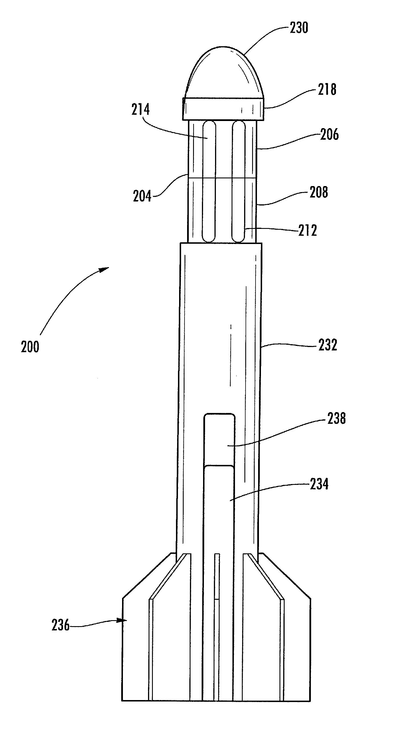
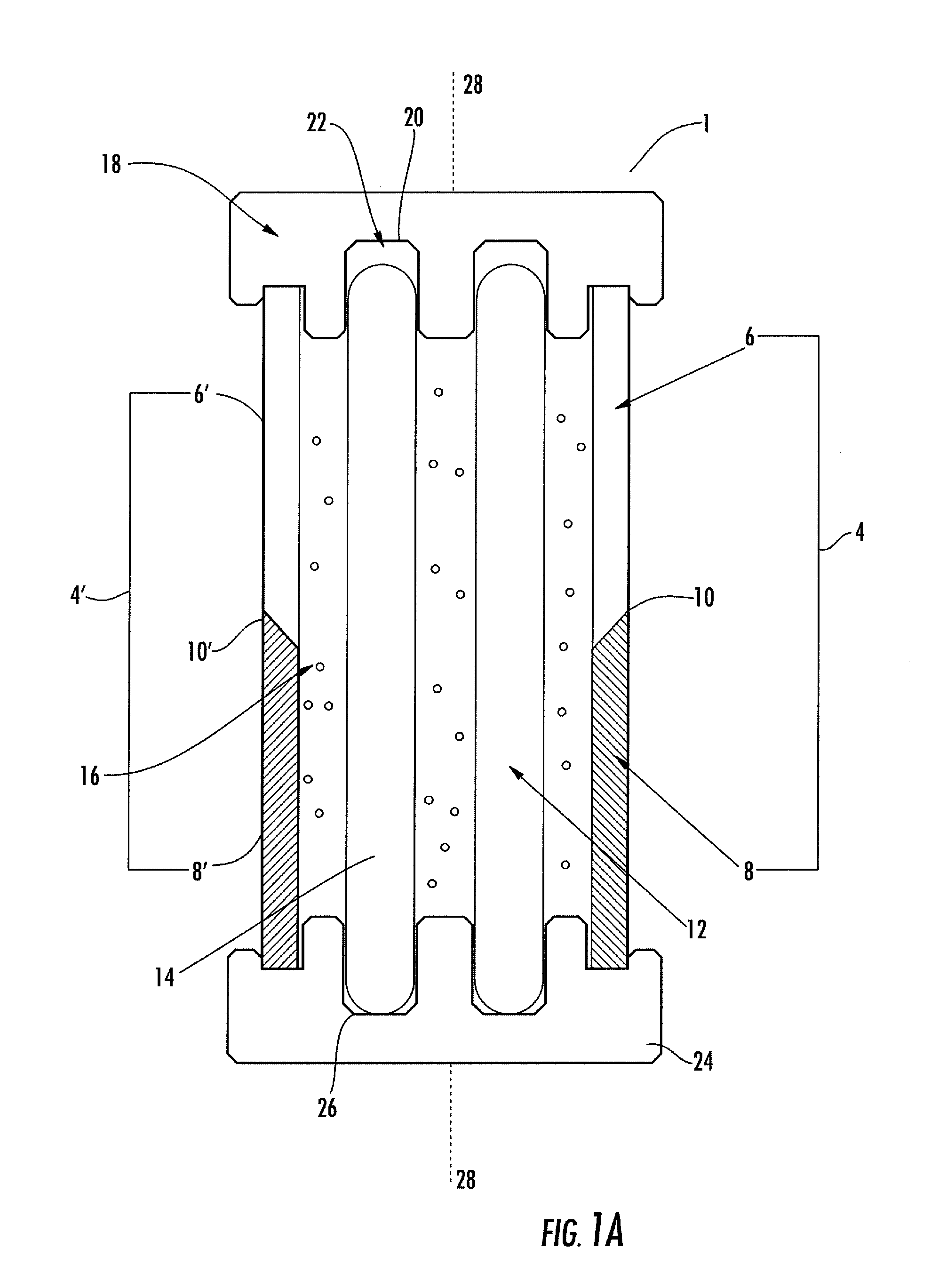
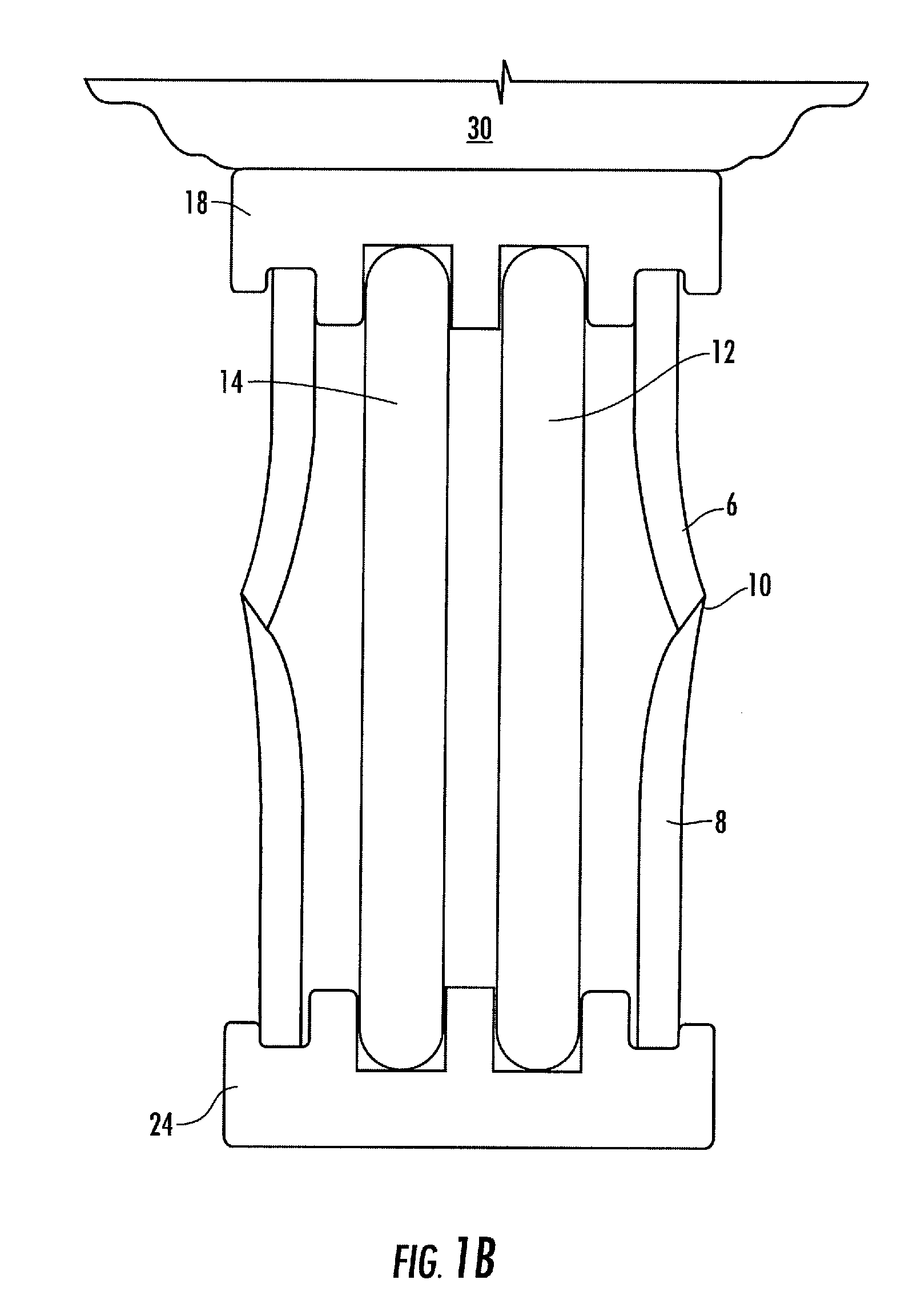
[0046]The present invention discloses a non-pyrotechnic, light emitting projectile for marking and illuminating a target. The projectile generally contains a main body having frangible side walls, at least one frangible ampoule containing chemiluminescent reactant components, a substantially incompressible filler material positioned between the frangible side walls and at least one ampoule, and a first and second end cap. The first end cap is constructed and arranged to connect to a portion of the frangible side walls and to receive a portion of the ampoules. The first end cap is designed to be traversable between a first position and a second position upon impact with an object. The traversal between the first position and the second position provides a force sufficient to rupture the frangible side walls. The force produced further ruptures the ampoules, causing intermixing of the chemiluminescent reactant components to produce light. The chemiluminescent reactant components furth...


PUM


Abstract

The present invention discloses a non-pyrotechnic, light emitting projectile for marking and illuminating a target. The projectile generally contains a main body having frangible side walls, at least one frangible ampoule containing chemiluminescent reactant components, a substantially incompressible filler material positioned between the frangible side walls and ampoule, and a first and second end cap. The first end cap is designed to be traversable between a first position and a second position upon impact with an object, thus provides a force sufficient to rupture the frangible side walls and ampoules. Rupture of the ampoules causes intermixing of the chemiluminescent reactant components and formation of a chemiluminescent slurry. The second end cap provides sufficient energy transfer to the chemiluminescent slurry upon impact with a target to disperse the chemiluminescent slurry radially and outwardly with respect to the longitudinal axis of the main body.

Description

FIELD OF THE INVENTION[0001]This invention relates to light producing projectiles, particularly to deployable, non-pyrotechnic, chemiluminescent light emitting projectiles for marking or illuminating a target which disperses its contents upon impact in a radially and outwardly direction with respect to the longitudinal axis of the projectile for use in tactical and training exercises.BACKGROUND OF THE INVENTION[0002]Military and law enforcement personnel worldwide employ a variety of grenade devices, both hand thrown and rifle launched. Payloads include lethal and non lethal explosive charges, chemical agents such as tear gas, smoke, and combinations of elements to create a blinding light and loud noise to disrupt the target (“flash-bang”). Other versions provide a pyrotechnic light source to illuminate an area or target for remote reconnaissance. In addition, in the training of military and law enforcement personnel, a need exists for detecting the accuracy and effectiveness of the...

Claims


Application Information

Patent Timeline
IPC IPC(8): F21K2/06
CPCF42B12/42F42B12/40
Inventor LONGO, JOSEPH COSIMO
Owner CYALUME TECH
Learn More