
Roots supercharger with a shunt pulsation trap

a supercharger and pulsation trap technology, applied in the direction of machines/engines, liquid fuel engines, rotary/oscillating piston pump components, etc., can solve the problems of pulsation control, huge pressure and flow pulsations, and impede the expansion of commercial applications, etc., to achieve compact size, less noise, and light weight

Inactive Publication Date: 2012-01-26
HUANG PAUL XIUBAO +1
View PDF38 Cites 25 Cited by
  • Summary
  • Abstract
  • Description
  • Claims
  • Application Information

AI Technical Summary

Benefits of technology

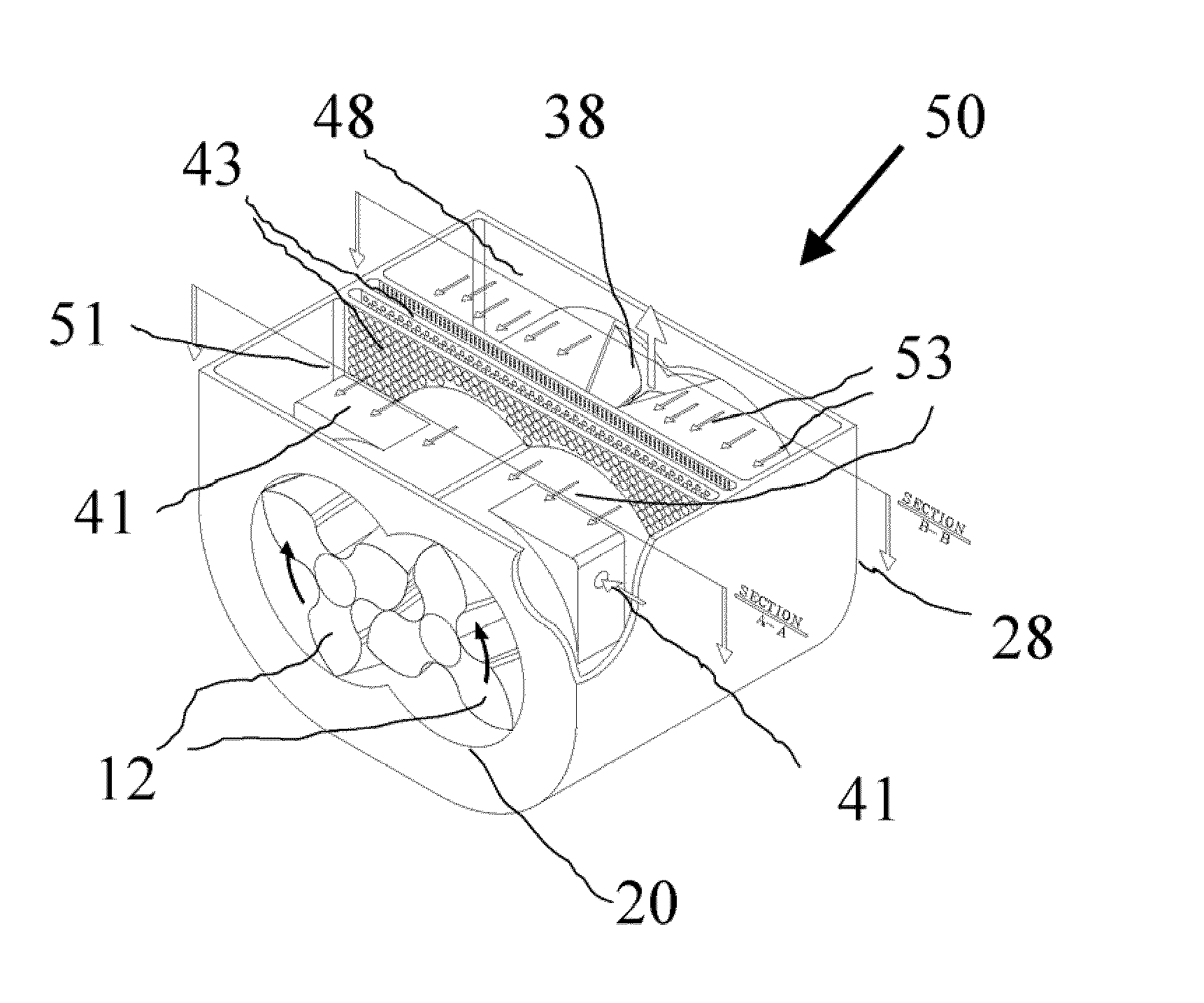
[0020]It is a further object of the present invention to provide a Roots supercharger with a shunt pulsation trap as an integral part of the supercharger casing that does not need an externally connected pulsation dampener or silencer so that it remains light in weight and compact in size with less noise radiation surfaces.
[0021]It is a further object of the present invention to provide a Roots supercharger with a shunt pulsation trap that emits pulsation free gases downstream hence reduce fatigue failure of downstream components.
[0022]It is a further object of the present invention to provide a Roots supercharger with a shunt pulsation trap that is capable of achieving all the above objectives in a wide range of engine operating speeds and loads.
[0023]It is a further object of the present invention to provide a Roots supercharger with a shunt pulsation trap that is capable of achieving higher adiabatic efficiency in the range equivalent or close to conventional turbocharger or dry screw supercharger, say up to about 80%.

Problems solved by technology

Despite the above mentioned generally attractive features for Roots potentials, several challenges have impeded their extensive commercial applications.
Among them, the number one issue is pulsation control.
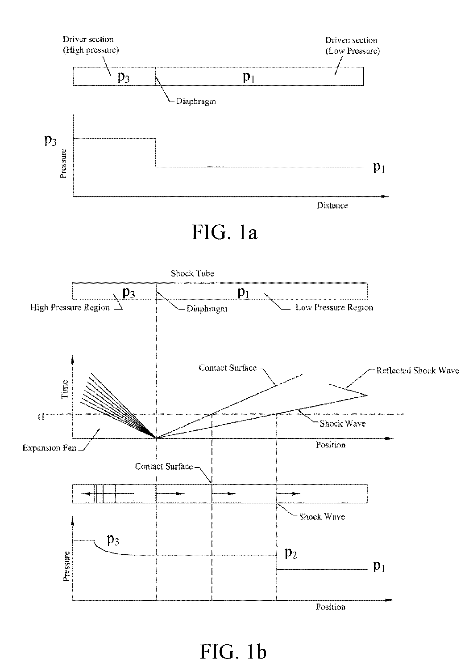
Those large amplitude expansion waves combined with the reflected pressure wave or shockwaves from the lobe cells, if not blocked or treated, could travel downstream, creating huge pressure and flow pulsations and induced vibrations that could destroy downstream components, or generate noises as high as 170 dB for high pressure applications.
It is generally very effective in pulsation control but requires large size to be effective, not suitable for mobile applications such as automobiles and trucks.
At the same time, discharge dampeners used today could create high pressure losses that contribute to poor supercharger efficiency.
Various attempts have been made to reduce Roots pulsations throughout years, but only limited successes have been achieved.
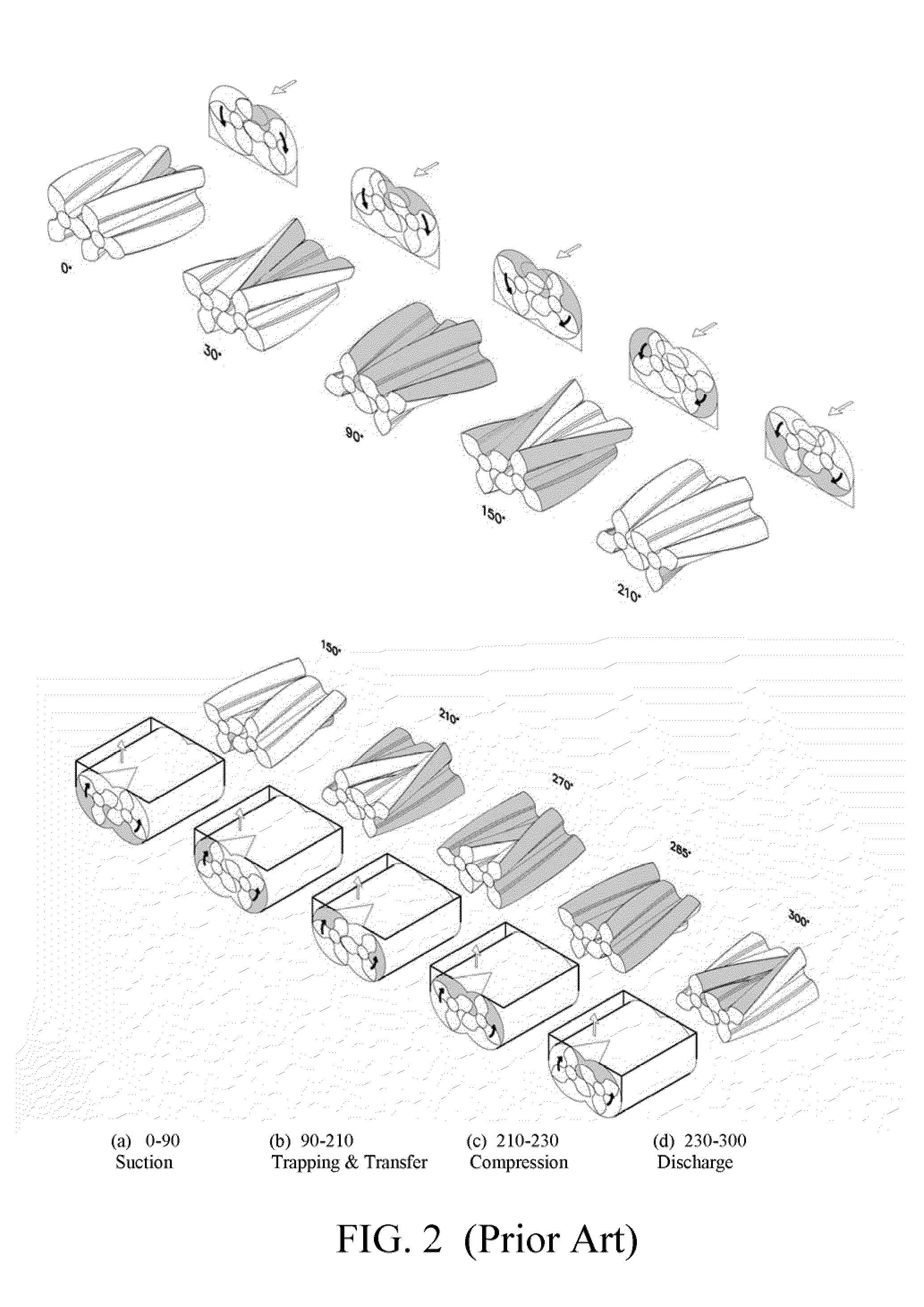
The main reason for this failure is believed to be lacking an adequate Roots compression mechanism that could point to the root cause of pulsations.
However, its effectiveness for pulsation attenuation is limited because it fails to recognize that the waves, not fluid flow, are the primary cause of the air-borne pulsations.
However, it failed to recognize hence attenuate the simultaneously generated expansion waves at the injection port that eventually travel down-stream unblocked, causing high pulsations.
Moreover, the prior art failed to address the high flow losses associated with the high induced jet velocity through the injection port, resulting in a low supercharger efficiency that hampers it from being used more widely to more energy sensitive applications.
Since the amplitude of pressure pulsation in a supercharger is typically much higher than the upper limit of 140 dB set in classical acoustics, the small disturbance assumption or the resulting linear theory is inadequate to predict its behavior.
It is this large pressure forces and induced high velocity fluid flow that could directly damage a system and components on its travelling path, in addition to exciting vibrations and noises.

Method used


Image

  • Roots supercharger with a shunt pulsation trap
  • Roots supercharger with a shunt pulsation trap
  • Roots supercharger with a shunt pulsation trap

Examples


Embodiment Construction

)

[0039]Although specific embodiments of the present invention will now be described with reference to the drawings, it should be understood that such embodiments are examples only and merely illustrative of but a small number of the many possible specific embodiments which can represent applications of the principles of the present invention. Various changes and modifications obvious to one skilled in the art to which the present invention pertains are deemed to be within the spirit, scope and contemplation of the present invention as further defined in the appended claims.

[0040]It should also be pointed out that though drawing illustrations and description are devoted to a helical three-lobe Roots supercharger in the present invention, the principle can be applied to other types of rotary supercharger with different numbers of lobes such as four-lobed, five-lobed or six lobed, etc. as long as both rotors have the same number of lobes. The principle can also be applied to either gas...


PUM


Abstract

A shunt pulsation trap for a Roots supercharger reduces pulsation, NVH and improves efficiency without significantly increasing overall size of the supercharger. Generally, a Roots supercharger with the shunt pulsation trap has a pair of interconnected and synchronized parallel multi-helical-lobe rotors housed in a transfer chamber with the same number of lobes for propelling flow from a suction port to a discharge port of the transfer chamber without internal compression. The shunt pulsation trap comprises an inner casing as an integral part of the transfer chamber, and an outer casing oversized surrounding the inner casing, therein housed various pulsation dampening means or pulsation energy recovery means or pulsation containment means, at least one injection port (trap inlet) branching off from the transfer chamber into the pulsation trap chamber and a feedback region (trap outlet) communicating with the supercharger outlet pressure.

Description

CLAIM OF PRIORITY[0001]This application claims priority to Provisional U.S. patent application entitled ROOTS SUPERCHARGER WITH A SHUNT PULSATION TRAP, filed Jul. 20, 2010, having application No. 61 / 366,140, the disclosure of which is hereby incorporated by reference in its entirety.BACKGROUND OF THE INVENTION[0002]1. Field of the Invention[0003]The present invention relates generally to the field of rotary blowers or compressors used in automotive supercharging applications, and more particularly relates to a double rotor helical shaped multi-lobe type commonly known as Roots blowers or superchargers (other often used names are rotary PDs, rotary lobe or rotary piston types), and more specifically relates to a shunt pulsation trap for reducing pulsations and induced vibration, noise and harshness (NVH) from such superchargers for internal combustion engines.[0004]2. Description of the Prior Art[0005]Ever since German engineer Gottlieb Daimler filed the first patent in late 19th cen...

Claims


Application Information

Patent Timeline
Patent Type & Authority Applications(United States)
IPC IPC(8): F01C21/00
CPCF01C1/086F04C29/0035F04C18/16F01C21/10
Inventor HUANG, PAUL XIUBAOYONKERS, SEAN WILLIAM
Owner HUANG PAUL XIUBAO
Learn More