Electronic Locking Differential

a technology of electronic locking differential and winding, which is applied in mechanical actuated clutches, transportation and packaging, and machining, etc., can solve the problems of insufficient engagement force of the number of windings, and achieve the effect of reducing weight and cost, moving a short distance, and small copper winding

Inactive Publication Date: 2012-01-26
FORD GLOBAL TECH LLC
View PDF13 Cites 39 Cited by
  • Summary
  • Abstract
  • Description
  • Claims
  • Application Information

AI Technical Summary

Benefits of technology

[0010]The locking differential employs a relatively small coil having a small copper winding, thereby reducing its weight and cost.
[0011]The locking differential amplifies displacement of the energized coil, thereby allowing the coil to move a short distance while providing a large movement for the lock

Problems solved by technology

Due to packaging constraints, however, certain vehicle applications require a small electromagnetic coil whose s

Method used


Image

  • Electronic Locking Differential
  • Electronic Locking Differential
  • Electronic Locking Differential

Examples


Embodiment Construction

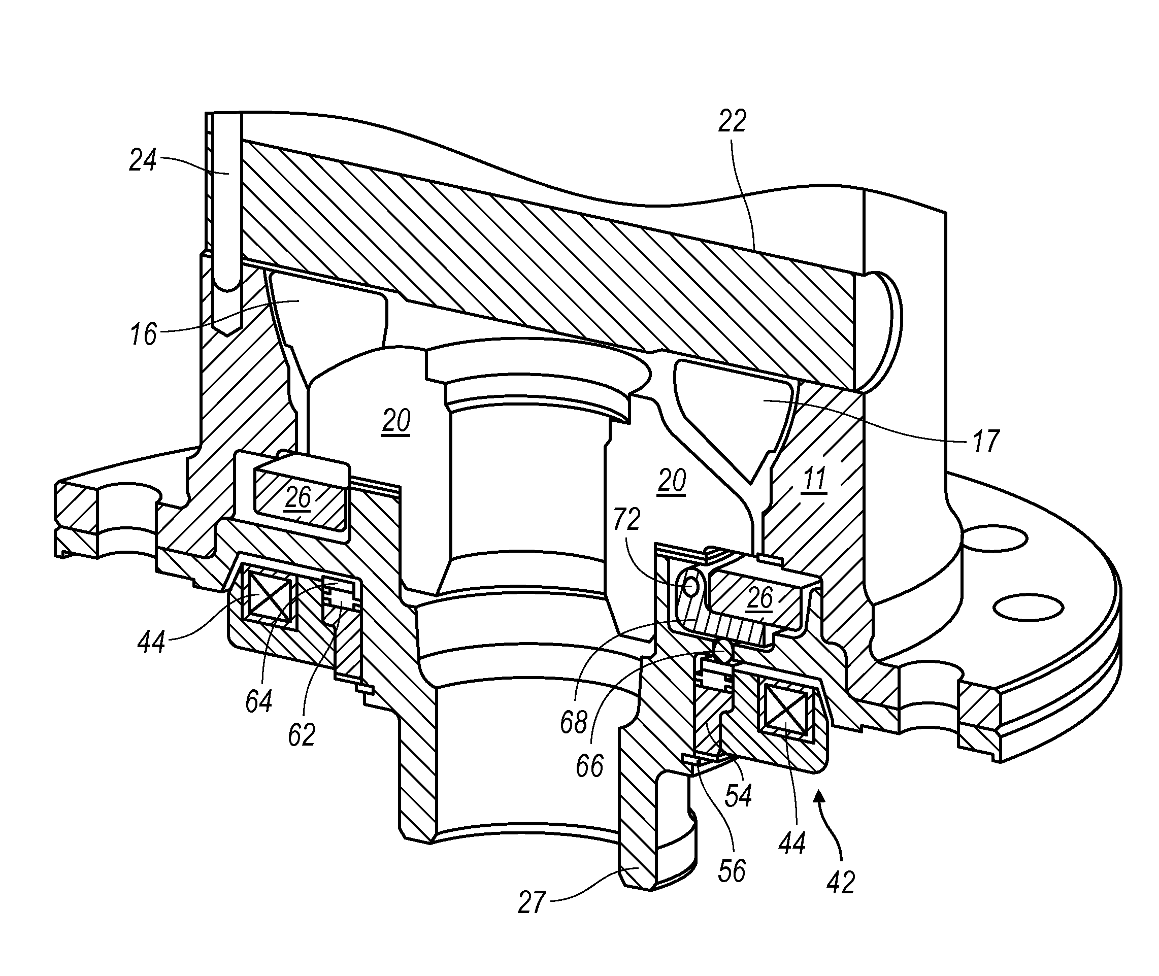
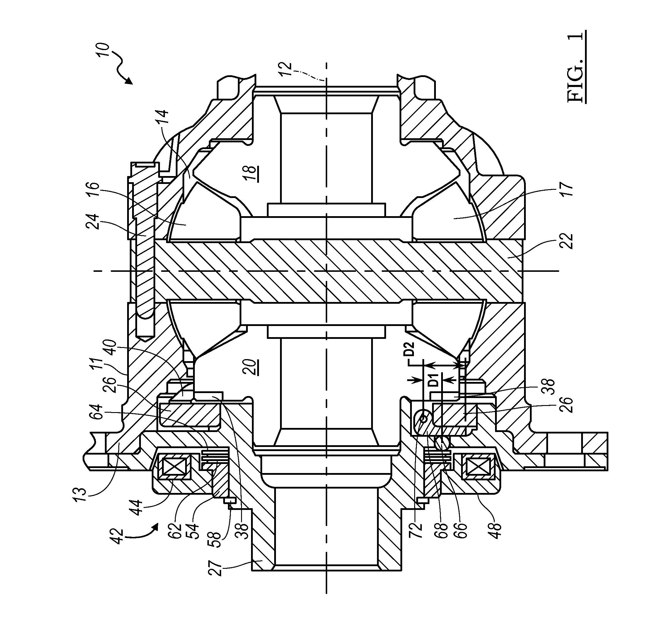
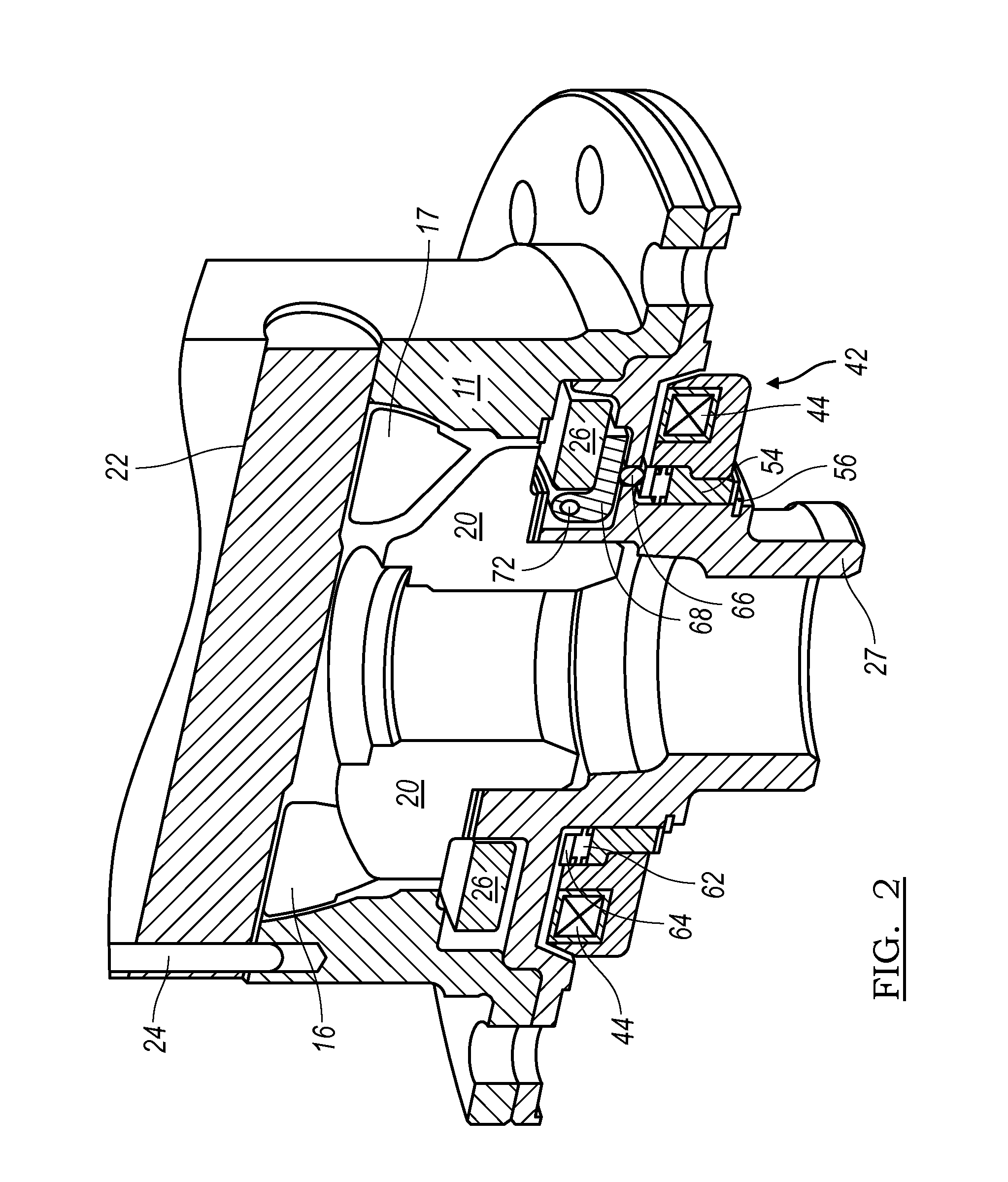
[0024]Referring to FIGS. 1 and 2, a differential mechanism 10 includes a differential case 11, preferably of cast iron or steel, supported on a stationary housing (not shown) for rotation about a lateral axis 12. The case 11 is driveably connected through a bevel ring gear (not shown) to the output of a transmission or transfer case. The ring gear, secured to the case 11 at the attachment bolt holes on a flange 13, is supported for rotation about axis 12.

[0025]The case 11 provides an internal chamber 14, which contains bevel pinions 16, 17. Chamber 14 contains a right-side bevel gear 18 meshing with the pinions 16, 17, driveably connected to an output shaft and secured by a spline to side gear 18, which extends laterally at the right-hand side from the case 11 to a driven wheel of a motor vehicle. Chamber 14 contains a left-side bevel gear 20 meshing with the pinions 16, 17, driveably connected to a second output shaft and secured by a spline to side gear 20, which extends laterally...


PUM


Abstract

A differential mechanism includes a case, a gear rotatable about an axis, a lock ring held against rotation relative to the case, a lever contacting the lock ring, and an electromagnetic coil that is displaced axially when energized, pivoting the lever, engaging the lock ring with the side gear, and preventing the gear from rotating relative to the case.

Description

BACKGROUND OF THE INVENTION[0001]1. Field of the Invention[0002]The present invention relates generally to an apparatus for alternately releasing and holding a side gear of a differential assembly against rotation relative to a case. More particularly, the invention pertains to electromagnetic actuation of a device for releasing and holding the side gear.[0003]2. Description of the Prior Art[0004]A locking differential is used to prevent relative rotation of one driven wheel with respect to another driven wheel. This is usually accomplished by locking one differential side gear to a differential case, thereby preventing rotation of the side gear with respect to the differential case and preventing a wheel speed differential on any one axle.[0005]A locking differential employs hydraulic pressure or an electromagnet to actuate a mechanism that alternately holds a side gear against rotation and releases the side gear to rotate freely. Due to packaging constraints, however, certain vehi...

Claims


Application Information

Patent Timeline
IPC IPC(8): F16H48/30
CPCF16H48/08F16H2048/346F16H48/34F16H48/24
Inventor ISKEN, II, DENNIS W.GUO, JIHONGANDONIAN, BRIAN J.POVIRK, JACOB M.HINDI, YASSER
Owner FORD GLOBAL TECH LLC
Why Eureka
Try Eureka