
Apparatus and method for measuring fluid viscosity

a technology of fluid viscosity and measuring apparatus, which is applied in the direction of liquid/fluent solid measurement, machines/engines, instruments, etc., can solve the problems of reduced testability, inability to use rotary viscometers, and small gap between outer cylinders and inner cylinders, so as to achieve precise flow rate and precise fluid viscosity, and enhance the convenience of use of the present invention.

Active Publication Date: 2012-01-26
CHUNG YUAN CHRISTIAN UNIVERSITY
View PDF8 Cites 9 Cited by
  • Summary
  • Abstract
  • Description
  • Claims
  • Application Information

AI Technical Summary

Benefits of technology

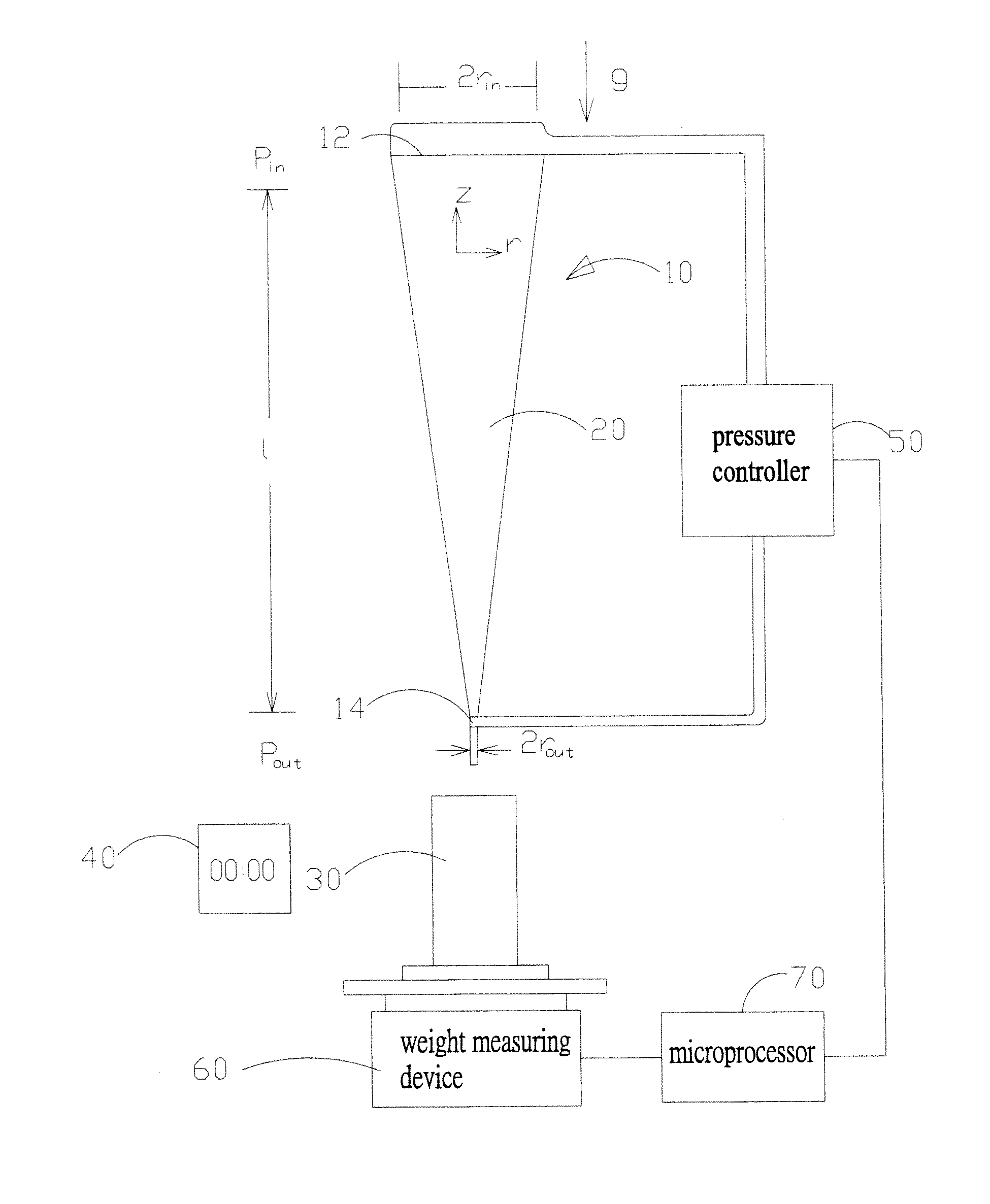
[0009]Therefore it is a primary object of the present invention to provide an apparatus and a method for measuring fluid viscosity. By a container in which an inlet end is larger than an outlet end, an equation is derived based on a fact that a viscosity value of the fluid is correlated with a flow rate value and a pressure gradient value. The flow rate is measured by a graduated cylinder and a timer. Then the viscosity is obtained according to the flow rate. Thus the testability is improved and the measurement time is reduced. Moreover, the present invention has simple structure so that maintenance and operation are quite easy. Not only the space required is less, the apparatus cost is low and the measurement error is reduced.
[0010]It is another object of the present invention to provide an apparatus and a method for measuring fluid viscosity in which a pressure controller for control of the pressure gradient of the fluid is connected to the inlet end and the outlet end so as to get more precise pressure gradient of the fluid and further obtain more precise viscosity of the fluid.
[0011]It is a further object of the present invention to provide an apparatus and a method for measuring fluid viscosity in which a weight measuring device measures weight of the fluid flowing out of the container and a timer measures a time required for the fluid to pass the outlet end. A more precise flow rate is obtained according to the weight, the time and a density of the fluid. A more precise viscosity of the fluid is further got.

Problems solved by technology

However, the gap between the outer cylinder and the inner cylinder is quite small.
Once the fluid contains granules therein such as slurry or suspension, the rotary viscometer doesn't work and its testability is reduced.
Thus the viscometer occupies space and costs a lot.
Furthermore, the length of two cylinders, the gap, location, the shape of the bottom of the cylinder, friction, and residual liquid all have effects on the measurement precision and cause increased measurement error.
Therefore the management and maintenance of the rotary viscometer are more difficult.
Moreover, up and down movements of the fluid level take a long time so that the measurement time is extended.
Furthermore, the movements of the liquid level in the two glass bulbs cause hydrostatic pressure changes at the outlet end and this influence the measurement precision and further the measurement error is increased.
In addition, the capillary diameter is quite small and difficult to be cleaned properly.
Thus the maintenance is getting difficult.
The liquid level moves freely in the two glass bulbs so that the operation for control of level movement is quite complicated.
Besides, once the liquid has high viscosity or granules whose diameter is closed to the capillary diameter, the glass capillary viscometer is not suitable.
And the capillary is an integrated tube produced with high technical cost.
Thus the high cost is still an issue.
However, it's difficult to observe and measure if the test liquid is not clean and transparent.
The testability is still not improved.
Moreover, the ball size compared with the vertical tube, the surface deterioration and abrasion all have affects on the measurement precision.
Thus the measurement error is large.
The ball is a consumable and this causes difficulties in maintenance.

Method used


Image

  • Apparatus and method for measuring fluid viscosity
  • Apparatus and method for measuring fluid viscosity
  • Apparatus and method for measuring fluid viscosity

Examples


Embodiment Construction

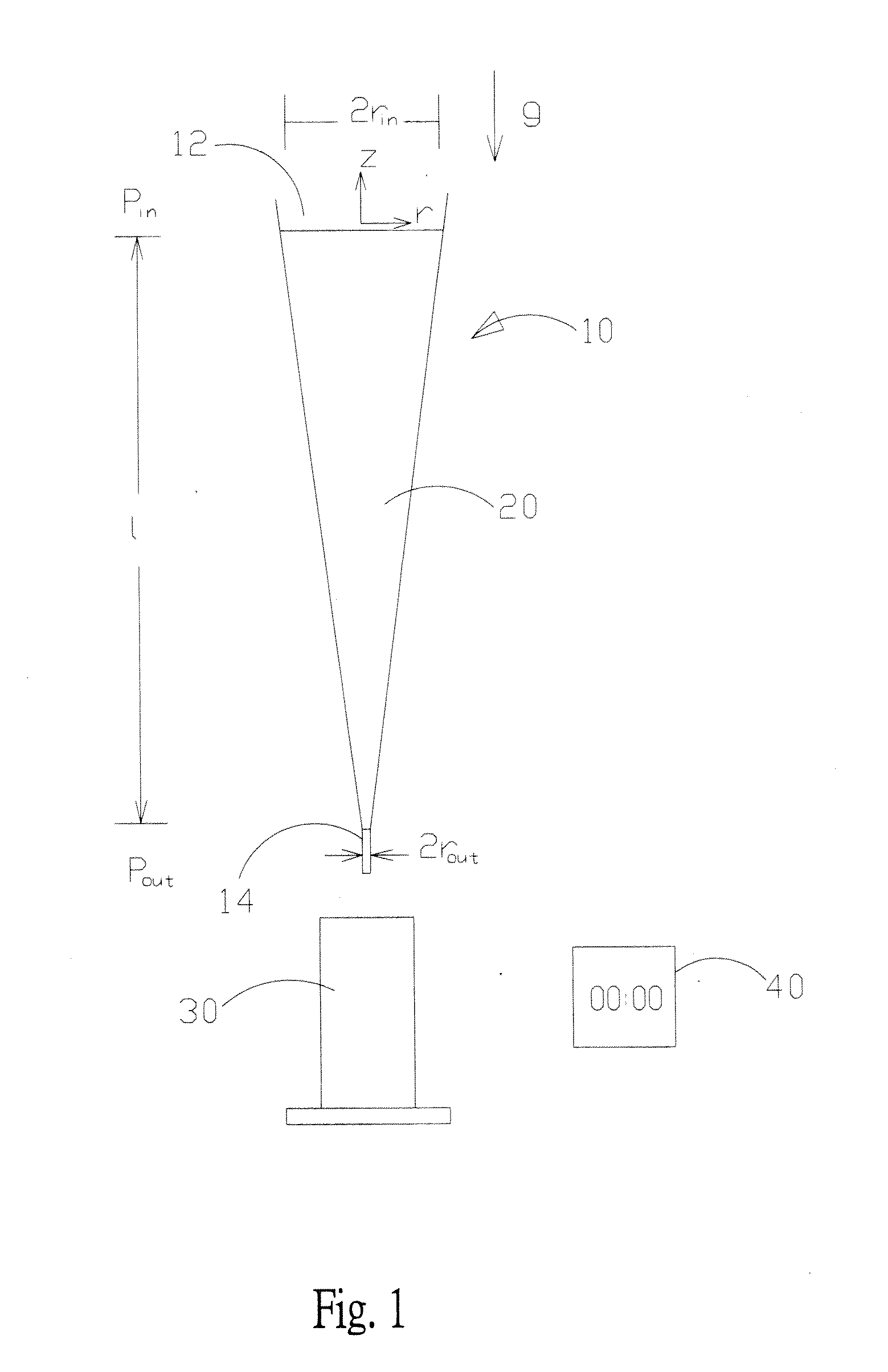
[0027]Refer to FIG. 1, an apparatus for measuring fluid viscosity of the present invention includes a container 10, a fluid 20, a graduated cylinder 30 and a timer 40. The container 10 is disposed with an inlet end 12 and an outlet end 14 while the inlet end 12 is larger than the outlet end 14. The fluid 20 is stored in the container 10. The container 10 of the present invention is a reducer in which the fluid 20 to be tested is placed. The fluid 20 is discharged through the outlet end 14 at a certain flow rate. The fluid 20 has a density value of ρ and a value of pressure gradient dp / dz. The fluid 20 at the inlet end 12 has an inlet pressure pin while the fluid 20 at the outlet end 14 has an outlet pressure pout. The difference between the inlet pressure pin and the outlet pressure pout divided by a height l of the container 10 is the value of pressure gradient dp / dz.

[0028]Due to gravity and inlet pressure difference between the inlet end and the outlet end, the fluid 20 jets freel...


PUM


Abstract

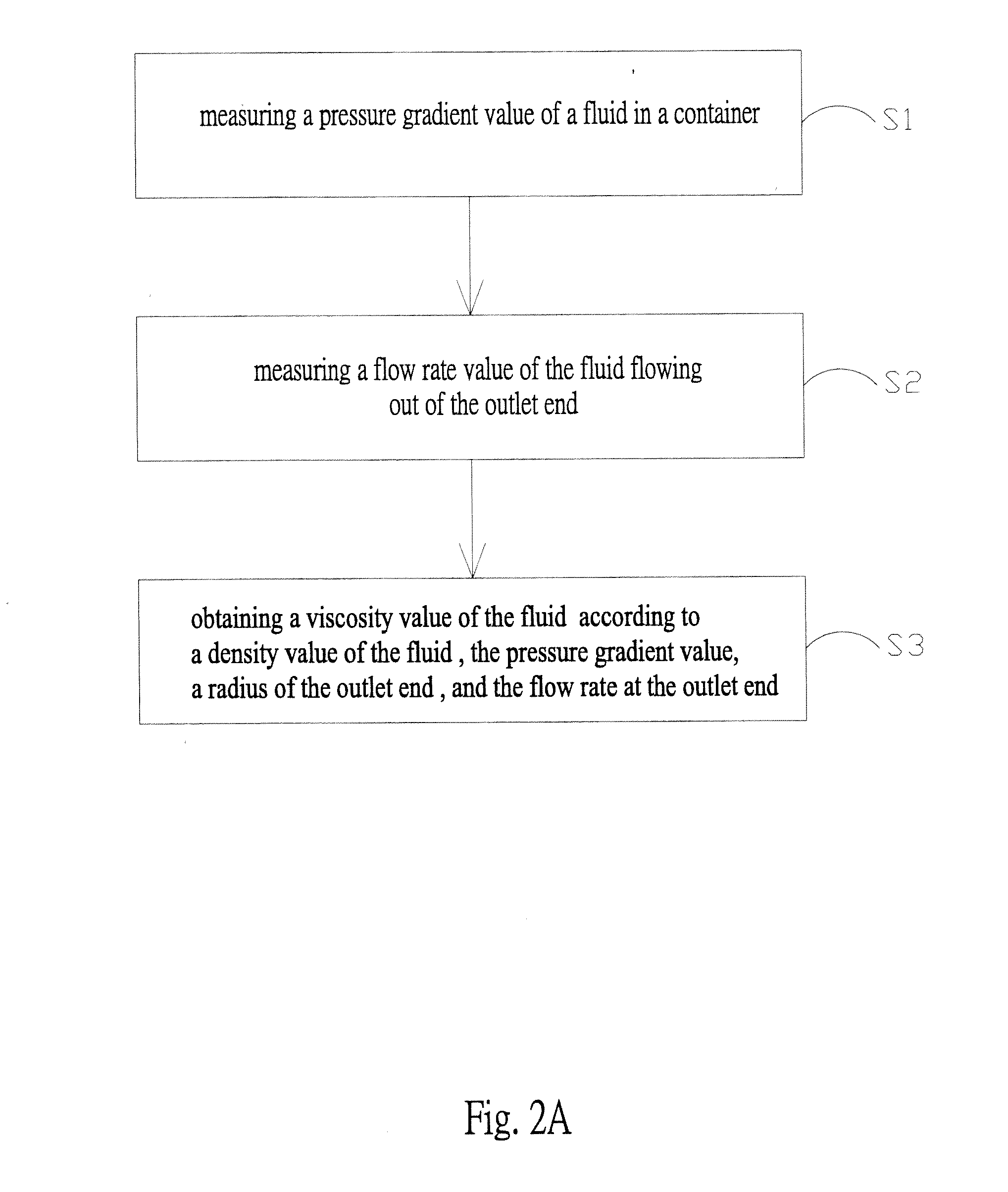
An apparatus and a method for measuring fluid viscosity are revealed. An inlet end of a container is larger than an outlet end of the container. A fluid flows through the outlet end at a flow rate. A volume of the fluid flowing out of the outlet end is measured by a graduated cylinder while the time taken for the fluid to flow through the outlet end is measured by a timer. The flow rate is associated with the volume and the time of the fluid and the viscosity of the fluid is obtained according to a density and a pressure gradient of the fluid, an outlet end radius and the flow rate. The apparatus has simple structure, easy operation and maintenance. Moreover, less space is required and the apparatus cost is low. Therefore, the testability is improved, the measurement time is reduced, and the convenience in use is enhanced.

Description

BACKGROUND OF THE INVENTION[0001]1. Fields of the invention[0002]The present invention relates to a measuring apparatus and a measuring method, especially to an apparatus and a method for measuring fluid viscosity.[0003]2. Descriptions of Related Art[0004]Viscosity is one of the important physical properties and is a measure of the resistance of a fluid. The more viscous the fluid is, the lesser its ease of movement. In our daily lives, there are phenomena related to the viscosity such as the taste of drinks, the degree of difficulty in painting, the writing fluency of a fountain pen. Among industrial technologies, there are also a lot of applications related to the viscosity such as a damping device, dip-feed lubrication, fuel oil transfer, and fuel oil atomization etc. The most common viscometers that measures fluid viscosity are rotary viscometers, glass capillary viscometers, and falling ball viscometer.[0005]A rotary viscometer, as revealed in U.S. Pat. No. 5,287,732, and No. 6...

Claims


Application Information

Patent Timeline
IPC IPC(8): G01N11/00G06F19/00
CPCG01N11/06
Inventor WENG, HUEI-CHUKAO, YUAN-KAI
Owner CHUNG YUAN CHRISTIAN UNIVERSITY
Learn More