Loop type pressure-gradient-drien low-pressure thermosiphon device

a thermosiphon device and gradient-driven technology, which is applied in the direction of indirect heat exchangers, lighting and heating apparatus, and semiconductor/solid-state device details, etc., can solve the problems of not being positively employed in heat exchangers for communication, home or industrial purposes, water cooling systems subject to the reliability of pumps, and possible leakage, etc., to achieve a wide range of heat transfer efficiency and high pressure , the effect of reducing the manufacturing cos

Active Publication Date: 2012-02-02
ASIA VITAL COMPONENTS SHENZHEN CO LTD
View PDF13 Cites 28 Cited by
  • Summary
  • Abstract
  • Description
  • Claims
  • Application Information

AI Technical Summary

Benefits of technology

[0013]In the loop type pressure-gradient-driven low-pressure thermosiphon device of the present invention, first flow passages are properly defined between adjacent flow-guiding members, so that overheated vapor is produced in the first flow passages, which are in contact with a heat source, to provide high pressure needed to drive steam-water circulation in the thermosiphon device. Further, with a proper pressure reduction design, a low-pressure end is form before the condensing section to produce a pressure gradient needed to drive steam-water circulation in the loop type pressure-gradient-driven low-pressure thermosiphon device. That is, with the present invention, no internal wick structure is needed to drive the working fluid in the case and the pipeline to transfer heat. In addition, the heat transfer efficiency of the present invention can be largely upgraded while the manufacturing cost thereof can be largely reduced.

Problems solved by technology

While the water cooling technique has already been widely applied in personal computers, it is not positively employed in heat exchangers for communication, home or industrial purpose.
That is, the water cooling system is subject to the reliability of the pump, possible leakage in the pipeline, and the like.
While the water cooling technique can be well applied to the personal computer that has a relatively large volume and is not subject to any spatial restriction, the water cooling technique for heat dissipation seems useless at all in terms of the communication chassis and home or industrial heat exchangers that are usually compact, low-profile and small in volume.
While the sintered layer provides a capillary force, it also increases an overall thickness of the heat pipe and the uniform temperature plate, preventing the latter from being effectively slimmed.
However, the above structure is not ideal for use because it involves in a very complicated manufacturing process and accordingly, increased manufacturing cost.
Since the conventional loop type thermosiphon device mainly employs capillary force and gravity force to drive steam-water circulation, it is subject to the limitation by gravity force.
Further, the loop type thermosiphon device has a relatively higher thermal resistance, and can only have a restricted rolling angle.
That is, there is a lot of limitation in the design and application of the conventional loop type thermosiphon device.
However, the heat pipe has limitation in its heat load, and accordingly, multiple pieces of heat pipes are frequently required to inevitably increase the cost of the personal computer and the RRU.
Meanwhile, the heat pipe may not necessarily have a thermal resistance that always satisfies the thermal resistance requirement for a central processing unit (CPU).
Moreover, the selection of a vapor core is not easy.
In brief, the prior art heat pipe or vapor chamber has the following disadvantages: (1) uneasy to fabricate; (2) unable to be slimmed; (3) high manufacturing cost; and (4) consuming time and labor to manufacture.

Method used


Image

  • Loop type pressure-gradient-drien low-pressure thermosiphon device
  • Loop type pressure-gradient-drien low-pressure thermosiphon device
  • Loop type pressure-gradient-drien low-pressure thermosiphon device

Examples


Embodiment Construction

[0024]The present invention will now be described with some preferred embodiments thereof and with reference to the accompanying drawings. For the purpose of easy to understand, elements that are the same in the preferred embodiments are denoted by the same reference numerals.

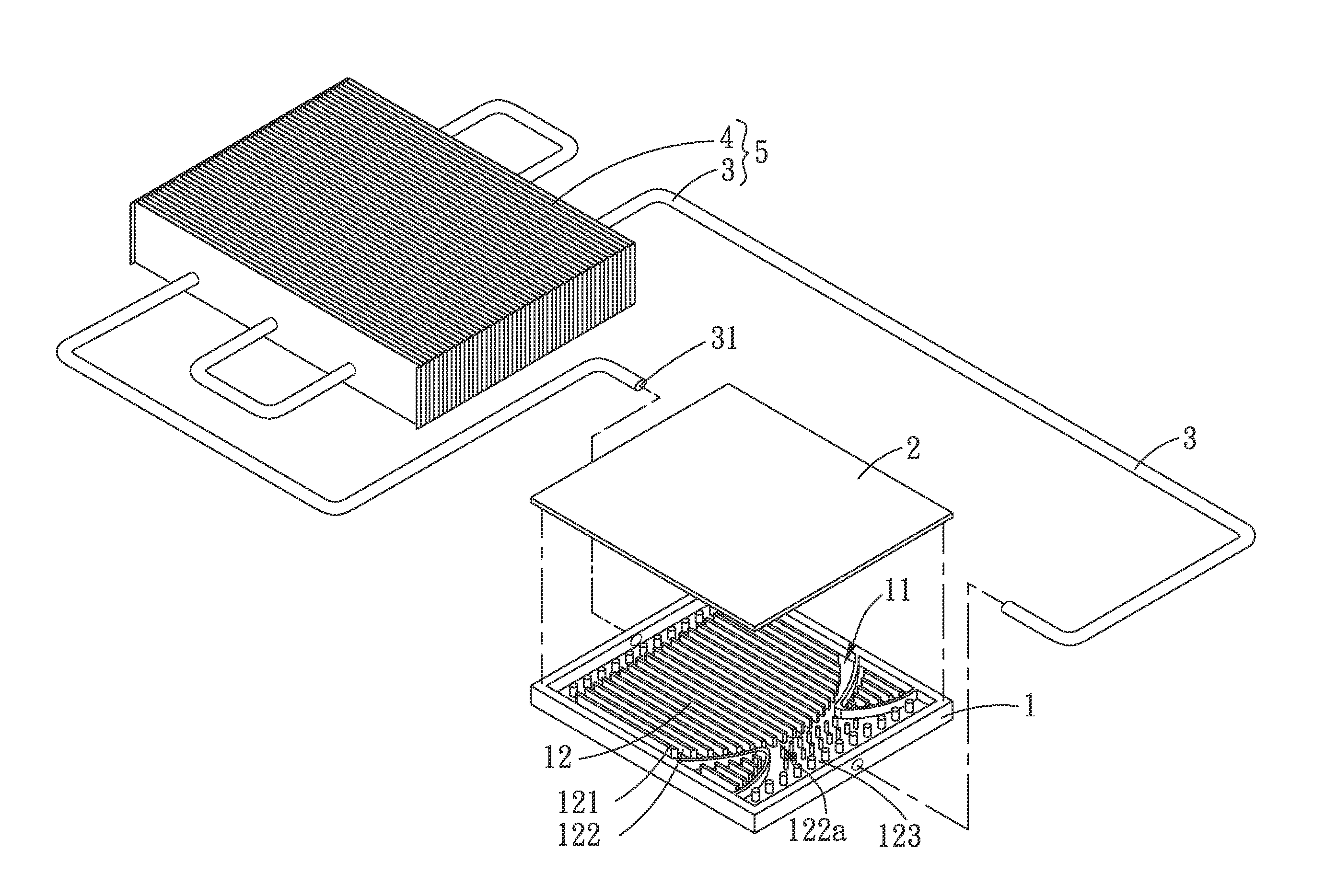
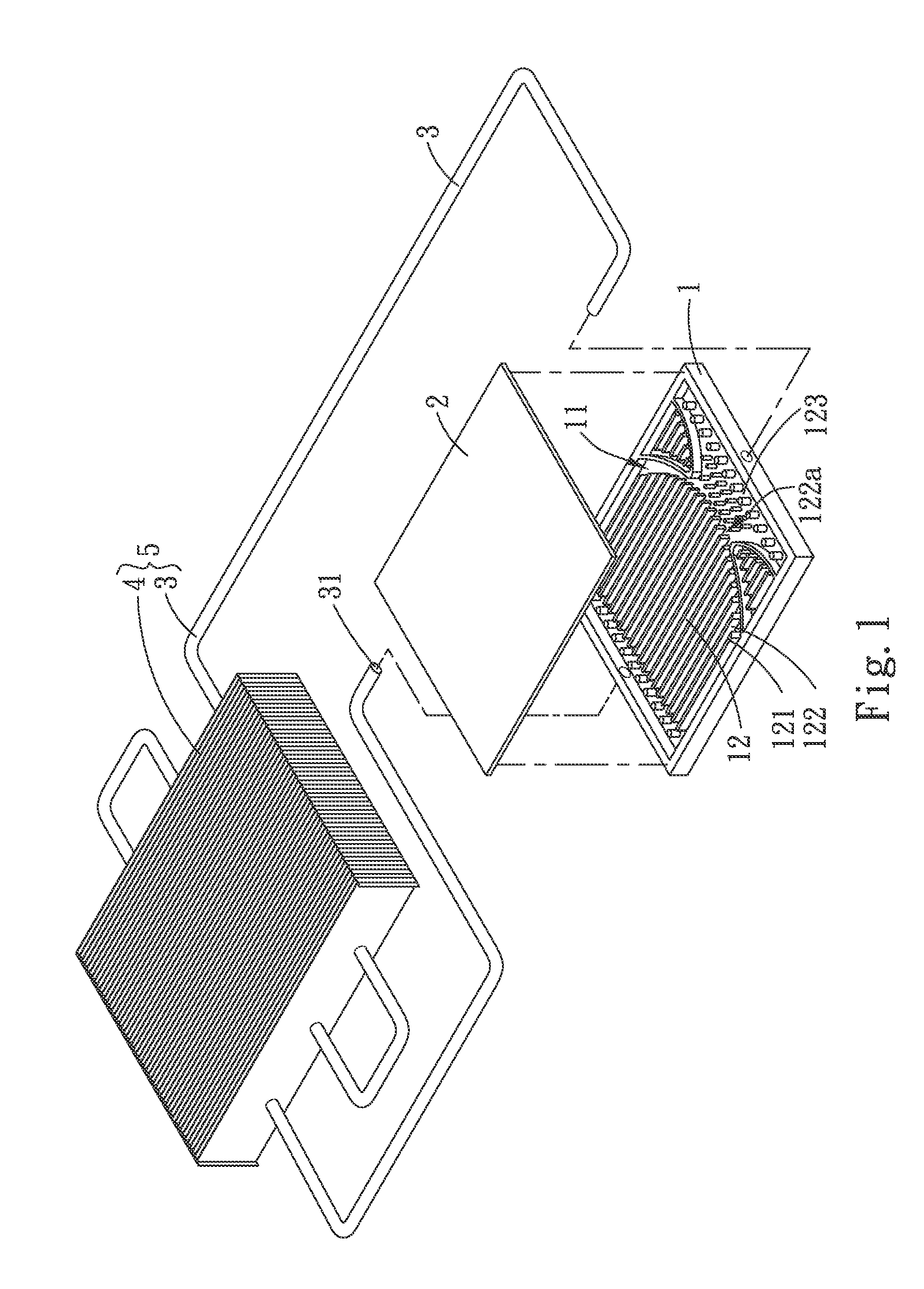
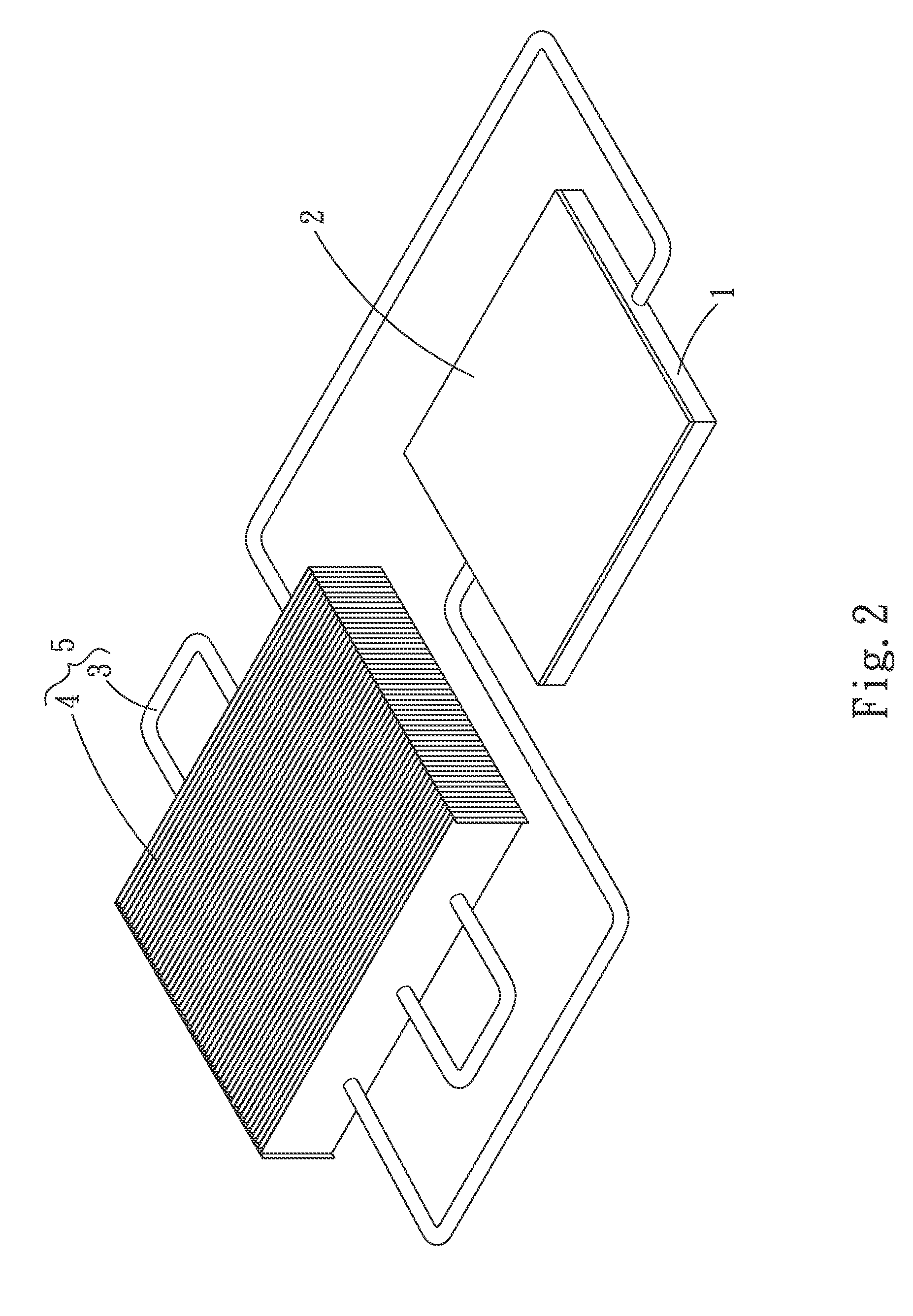
[0025]Please refer to FIGS. 1, 2 and 3. A loop type pressure-gradient-driven low-pressure thermosiphon device according to a first embodiment of the present invention includes a case 1, a cover 2, a pipeline 3, and at least one heat-dissipating element 4.

[0026]The case 1 defines a chamber 11. In the chamber 11, there is provided a vaporizing section 12. The vaporizing section 12 includes a plurality of flow-guiding members 121 being arrayed to space from one another, such that at least one first flow passage 122 is formed between any two adjacent flow-guiding members 121. The first flow passages 122 respectively have at least one free end 122a communicating with a free zone 123 in the chamber 11.

[0027]In the il...


PUM


Abstract

A loop type pressure-gradient-driven low-pressure thermosiphon device includes a case sealed by a cover to define a chamber with a vaporizing section. The vaporizing section includes a plurality of spaced flow-guiding members and first flow passages formed between adjacent flow-guiding members. The flow passages respectively have at least one free end communicating with a free zone in the chamber. A pipeline is connected at two ends to two opposite sides of the case, and has a second flow passage communicable with the vaporizing section. The pipeline extends through at least one heat-dissipating element, so that the pipeline and the heat-dissipating element together define a condensing section. In the thermosiphon device, a low-pressure end is created through proper pressure-reduction design to form a pressure gradient for driving steam-water circulation, and the working fluid can be driven to circulate and transfer heat in the pipeline and the case without any wick structure.

Description

[0001]This application claims the priority benefit of Taiwan patent application number 099125256 filed on Jul. 30, 2010.FIELD OF THE INVENTION[0002]The present invention relates to a loop type pressure-gradient-driven low-pressure thermosiphon device, and more particularly to a loop type pressure-gradient-driven low-pressure thermosiphon device that enables enhanced steam-water circulation without the need of using any wick structure and has reduced thermal resistance.BACKGROUND OF THE INVENTION[0003]In recent years, with the prosperous development in the electronic semiconductor industry, the progress in the process technique and the trends in the market demands, all kinds of electronic devices have been designed to be compact, low-profile and light in weight. However, while the electronic devices have gradually reduced dimensions, they have increasing functions and computing ability. For example, home or business computers, communication chassis, and home or industrial heat exchan...

Claims


Application Information

Patent Timeline
Patent Type & Authority Applications(United States)
IPC IPC(8): F28D15/00F28F13/12F28F7/00
CPCF28F13/06F28D15/0266H01L2924/0002H01L2924/00H05K7/20336H05K7/20309H01L23/427
Inventor CHANG, SHYY-WOEICHIANG, KUEI-FENG
Owner ASIA VITAL COMPONENTS SHENZHEN CO LTD
Why Eureka
Try Eureka