Aircraft actuator control apparatus

Active Publication Date: 2012-02-02
NABLESCO CORP
View PDF4 Cites 18 Cited by
  • Summary
  • Abstract
  • Description
  • Claims
  • Application Information

AI Technical Summary

Benefits of technology

[0013]With this configuration, the state switching valves that switch the operating state of the actuators are configured such that their positions can be switched between the actuator connection position, the damping position, and the test orifice position to provide communication between each of the actuators and the test orifice circuit including the test orifice. Then, a performance test for the orifice is executed by comparing the operating speed of the actuator when the state switching valve is switched to the damping position with the operating speed of the actuator when the state switching valve is switched to the test orifice position. Accordingly, it is not necessary to install test pressure sensors respectively corresponding to the ports of the pairs of oil chambers of the actuators, and therefore it is possible to suppress an increase in the number of sensors. Also, signal wiring and a process

Problems solved by technology

However, to perform such a test, pressure sensors that are installed respectively corresponding to the ports of the pair of oil chambers of the actuator and that are used only for the test are required, leading to

Method used


Image

  • Aircraft actuator control apparatus
  • Aircraft actuator control apparatus
  • Aircraft actuator control apparatus

Examples


Embodiment Construction

[0035]Hereinafter, an embodiment for carrying out the present invention will be described with reference to the accompanying drawings. It should be appreciated that this embodiment can be widely applied to an aircraft actuator control apparatus including a plurality of hydraulically operated actuators that drive a control surface of an aircraft and a plurality of control systems that respectively control the operation of the plurality of actuators.

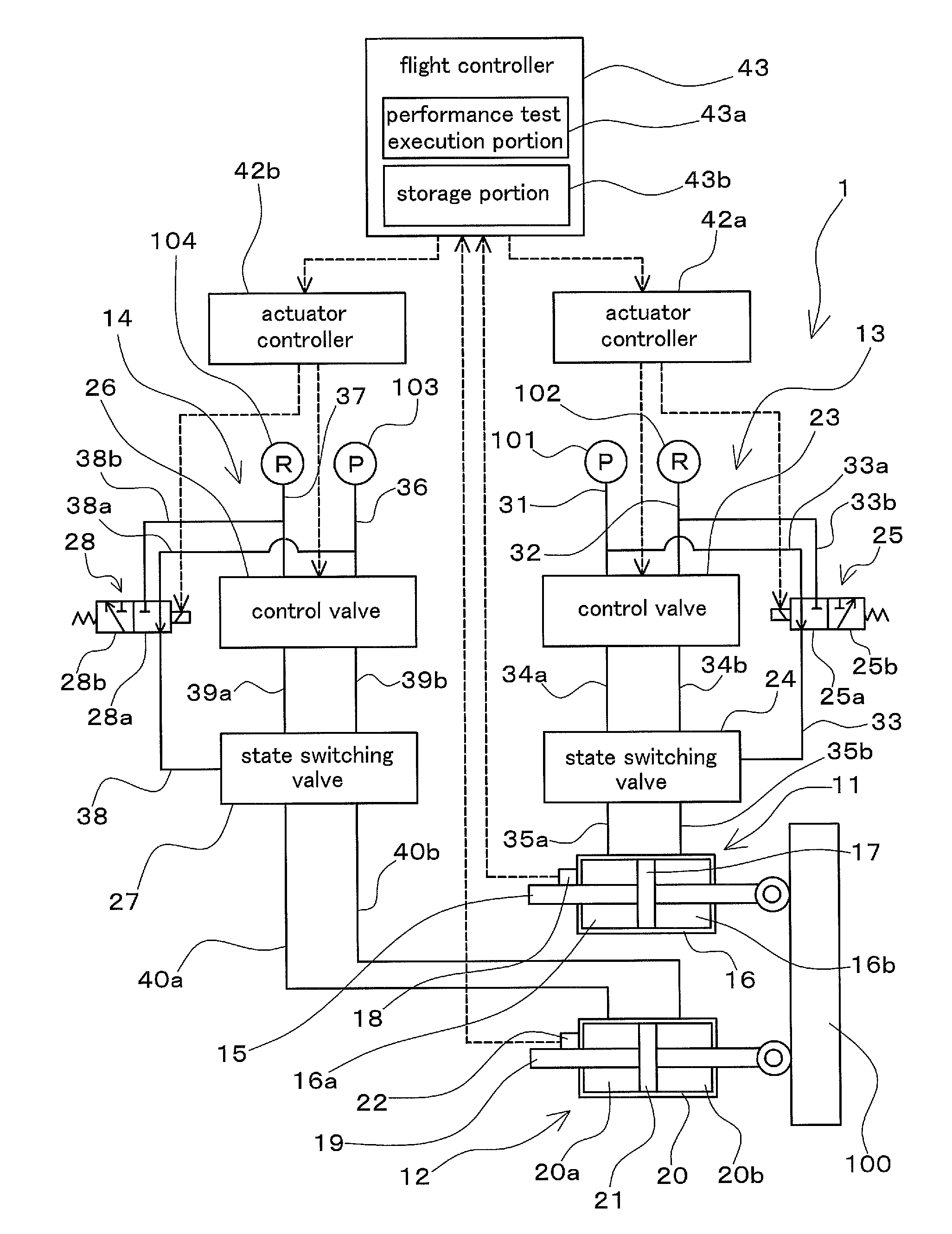
[0036]FIG. 1 is a hydraulic circuit diagram schematically showing an aircraft actuator control apparatus 1 according to one embodiment of the present invention. The aircraft actuator control apparatus 1 (hereinafter, also simply referred to as a “control apparatus 1”) includes a plurality of (in this embodiment, two) hydraulically operated actuators (11, 12) that drive a control surface 100 of an aircraft (not shown) and a plurality of control systems (13, 14) that respectively control the operation of the plurality of actuators (11, 12). ...


PUM


Abstract

A plurality of hydraulically operated actuators that drive a control surface and a plurality of control systems that respectively control the operation of the actuators are included. Each of the control systems includes a control valve, a state switching valve and a test orifice circuit. The test orifice circuit includes a test orifice used for testing the performance of an orifice. The state switching valve is provided such that its position can be switched between an actuator connection position, a damping position and a test orifice position.

Description

CROSS-REFERENCE TO RELATED APPLICATIONS[0001]This application claims priority to Japanese Patent Application No. 2010-173503. The entire disclosure of Japanese Patent Application No. 2010-173503 is hereby incorporated herein by reference.BACKGROUND OF THE INVENTION[0002]1. Field of the Invention[0003]The present invention relates to an aircraft actuator control apparatus including a plurality of hydraulically operated actuators that drive a control surface of an aircraft and a plurality of control systems that respectively control the operation of the plurality of actuators.[0004]2. Description of Related Art[0005]Conventionally, aircraft actuator control apparatuses are used that include a plurality of hydraulically operated actuators that drive a control surface of an aircraft and a plurality of control systems that respectively control the operation of the plurality of actuators. A known example of such an aircraft actuator control apparatus is the aircraft actuator control appar...

Claims


Application Information

Patent Timeline
IPC IPC(8): B64C13/26
CPCB64F5/0045B64C13/40B64F5/60B64C13/42
Inventor ITO, KOJITANAKA, TOSHIAKI
Owner NABLESCO CORP
Why Eureka
Try Eureka