Wireless power transmitter, wireless power receiver, and method for wireless power transfer using them

a wireless electric and receiver technology, applied in the direction of electromagnetic wave systems, transformers, inductances, etc., can solve the problem of extremely short effective range of magnetic induction, and achieve the effect of reducing charge tim

Active Publication Date: 2012-02-02
ELECTRONICS & TELECOMM RES INST
View PDF5 Cites 51 Cited by
  • Summary
  • Abstract
  • Description
  • Claims
  • Application Information

AI Technical Summary

Benefits of technology

[0006]The present invention also provides a wireless power transmitter and a wireless power receiver capable of reducing charge time, and a method for a wireless power transfer using them.

Problems solved by technology

A charger may be used; however, the electronic devices should be supplied with electric power through a wire again due to limitation of charge capacity after they are used for a certain period of time.
However, an effective range of the magnetic induction is extremely short causing various incommodities.

Method used


Image

  • Wireless power transmitter, wireless power receiver, and method for wireless power transfer using them
  • Wireless power transmitter, wireless power receiver, and method for wireless power transfer using them
  • Wireless power transmitter, wireless power receiver, and method for wireless power transfer using them

Examples


Embodiment Construction

[0035]Preferred embodiments of the present invention will be described below in more detail with reference to the accompanying drawings. The present invention may, however, be embodied in different forms and should not be constructed as limited to the embodiments set forth herein. Rather, these embodiments are provided so that this disclosure will be thorough and complete, and will fully convey the scope of the present invention to those skilled in the art.

[0036]Hereinafter, it will be described about an exemplary embodiment of the present invention in conjunction with the accompanying drawings.

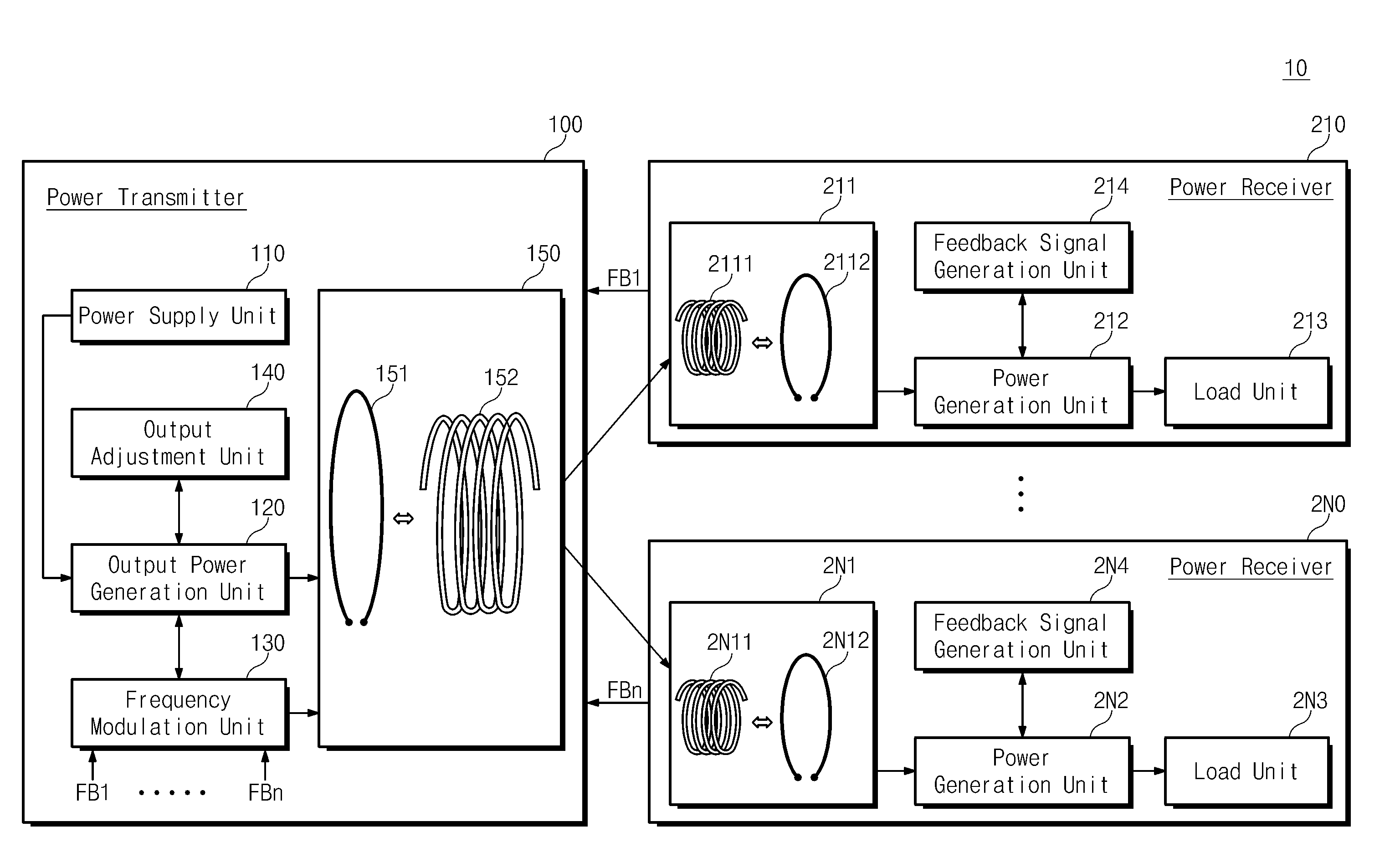
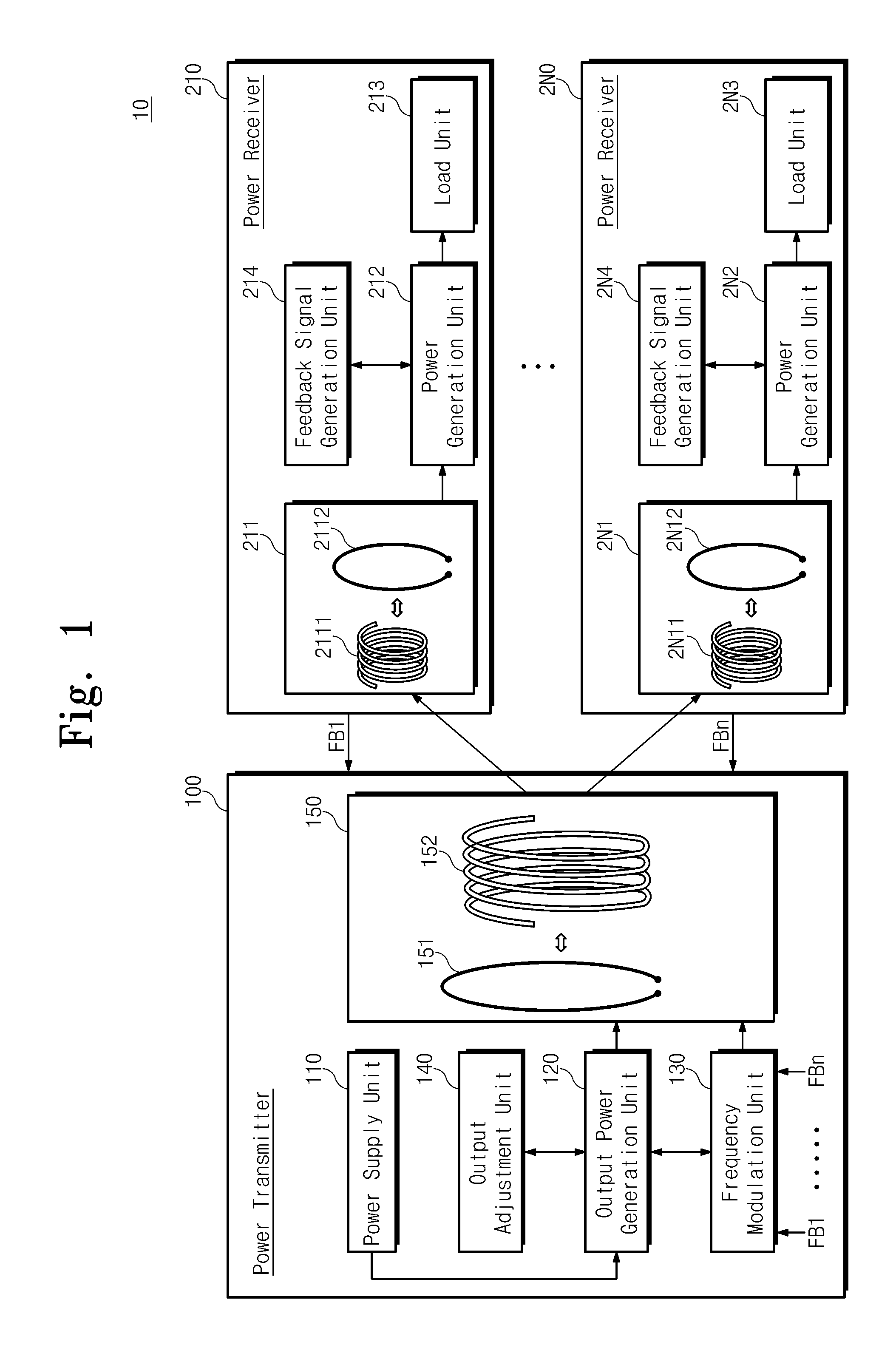
[0037]FIG. 1 is a block diagram illustrating a wireless power transfer system 10 according to an embodiment of the present invention. Referring to FIG. 1, the wireless power transfer system 10 includes a wireless power transmitter 100 and wireless power receivers 210 to 2N0, where N is a natural number.

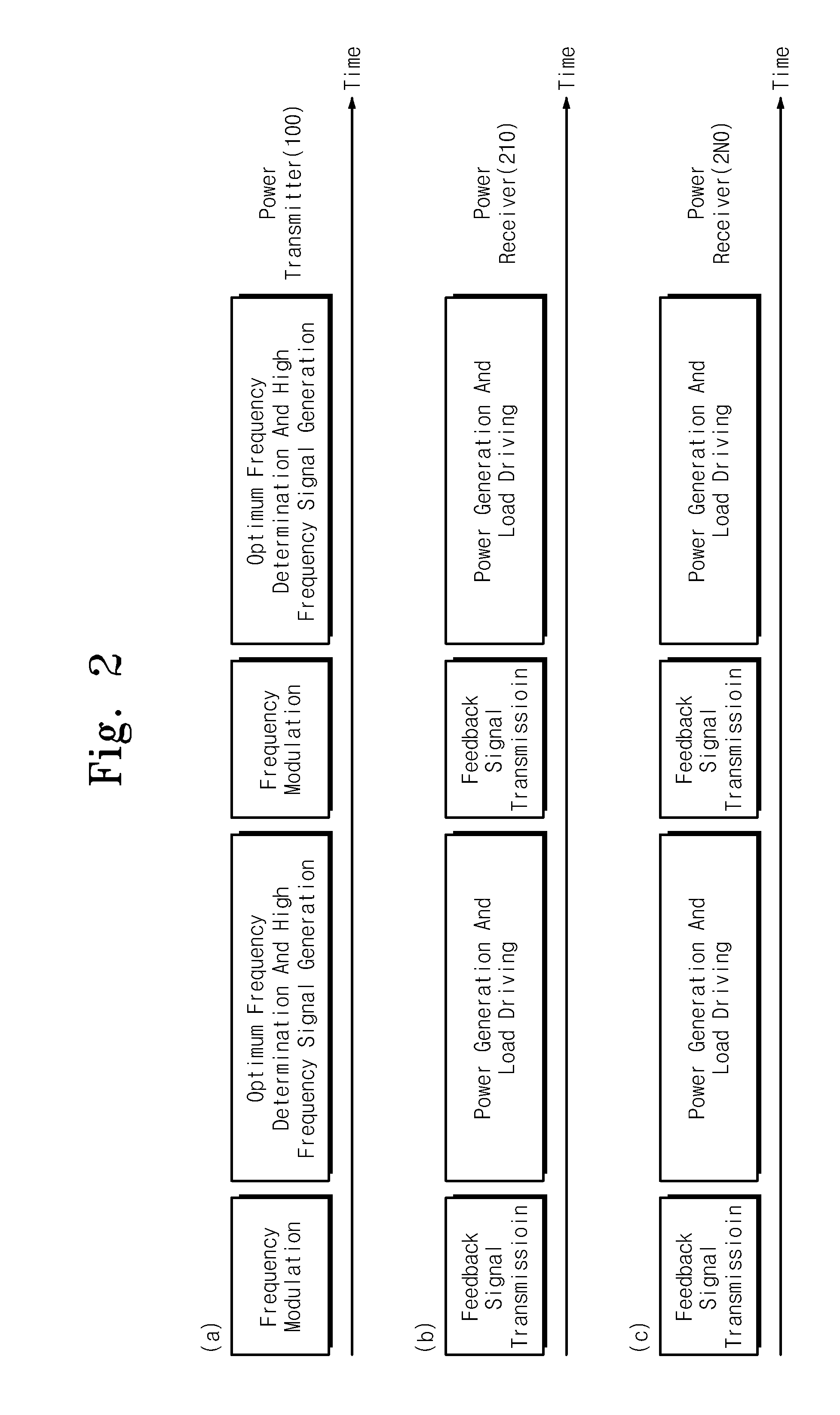
[0038]For the embodiment, the wireless power transfer system 10 may transfer power accordin...


PUM


Abstract

Provided is a method for a wireless power transfer. The method includes modulating a transmission frequency according to a predetermined value at a wireless power transmitter; and transmitting a high frequency signal according to the modulated transmission signal from the wireless power transmitter to at least one wireless power receiver and redetermining the predetermined value according to information which corresponds to a power value of the high frequency signal received by the at least one wireless power receiver, wherein the modulating the transmission frequency at the wireless power transmitter and transmitting the high frequency and the redetermining the predetermined value the at least one wireless power receiver are repeated.

Description

CROSS-REFERENCE TO RELATED APPLICATIONS[0001]This U.S. non-provisional patent application claims priority under 35 U.S.C. §119 of Korean Patent Application No. 10-2010-0073379, filed on Jul. 29, 2010, the entire contents of which are hereby incorporated by reference.BACKGROUND OF THE INVENTION[0002]The present invention disclosed herein relates to a wireless electric power transmitter, a wireless electric power receiver and a method of wireless electric power transfer using the same.[0003]Recently, performance and kinds of electronic devices have been remarkably improved and increased. Particularly, thanks to the remarkable development of the semiconductor and display technologies, portable electronic devices have been made smaller and smaller. However, one of shortcomings of the electronic devices is that they should be supplied with power through a wire. A charger may be used; however, the electronic devices should be supplied with electric power through a wire again due to limita...

Claims


Application Information

Patent Timeline
Patent Type & Authority Applications(United States)
IPC IPC(8): H02J17/00
CPCH02J5/005H02J50/80H02J50/40H02J50/10H02J50/12H02J7/0045H04B5/0075H04B5/0037
Inventor KIM, YONG HAEKANG, SEUNG YOULCHEON, SANG HOONLEE, MYUNG LAEZYUNG, TAE HYOUNG
Owner ELECTRONICS & TELECOMM RES INST
Why Eureka
Try Eureka