Motor for high temperature applications

a high-temperature application, motor technology, applied in the direction of synchronous motors, magnetised circuits, windings, etc., can solve the problem that most existing motors and actuators are not designed to survive in harsh high-temperature environments

Active Publication Date: 2012-02-02
HONEYBEE ROBOTICS
View PDF9 Cites 22 Cited by
  • Summary
  • Abstract
  • Description
  • Claims
  • Application Information

AI Technical Summary

Benefits of technology

[0005]A high temperature motor has a stator with poles formed by wire windings, and a rotor with magnetic poles on a rotor shaft positioned coaxially within the stator. The stator and rotor are built up from stacks of magnetic-alloy laminations. The stator windings are made of high temperature magnet wire insulated with a vitreous enamel film, and the wire windings are bonded together with ceramic binder. A thin-walled cylinder is positioned coaxially between the rotor and the stator to prevent debris from the stator windings from reaching the rotor. The stator windings are wound on wire spools made of ceramic, thereby avoiding need for mica insulation and epoxy / adhesive. The stator and rotor are encased in a stator housing with rear and front end caps, and rear and front bearings for the rotor shaft are mounted on external sides of the end caps to keep debris from the motor migrating into the bearings' races.
[0007]In one embodiment, these materials are integrated on a foundation of a switched reluctance motor (SRM). The SRM is doubly-salient, singly-excited, with salient poles on both the rotor and stator, but only the stator carries windings. The rotor has no windings, magnets, or cage winding. This minimizes the risk that the moving rotor will be susceptible to deterioration or failure while operating under high temperature, high pressure conditions. Both the rotor and the stator are built up from a stack of laminations made of a high temperature rare-earth permanent magnetic alloy. The purpose of the stacked laminations is to reduce eddy current losses during operation. The SRM employs electronic commutation, for which the magnetic field is stepped through the poles physically by sending current pulse sequences to the coils, so that the rotor follows this field.

Problems solved by technology

Most existing motors and actuators are not designed to survive in harsh high temperature environments.

Method used


Image

  • Motor for high temperature applications
  • Motor for high temperature applications
  • Motor for high temperature applications

Examples


Embodiment Construction

[0026]In the following detailed description of the invention, certain preferred embodiments are illustrated providing certain specific details of their implementation. However, it will be recognized by one skilled in the art that many other variations and modifications may be made given the disclosed principles of the invention.

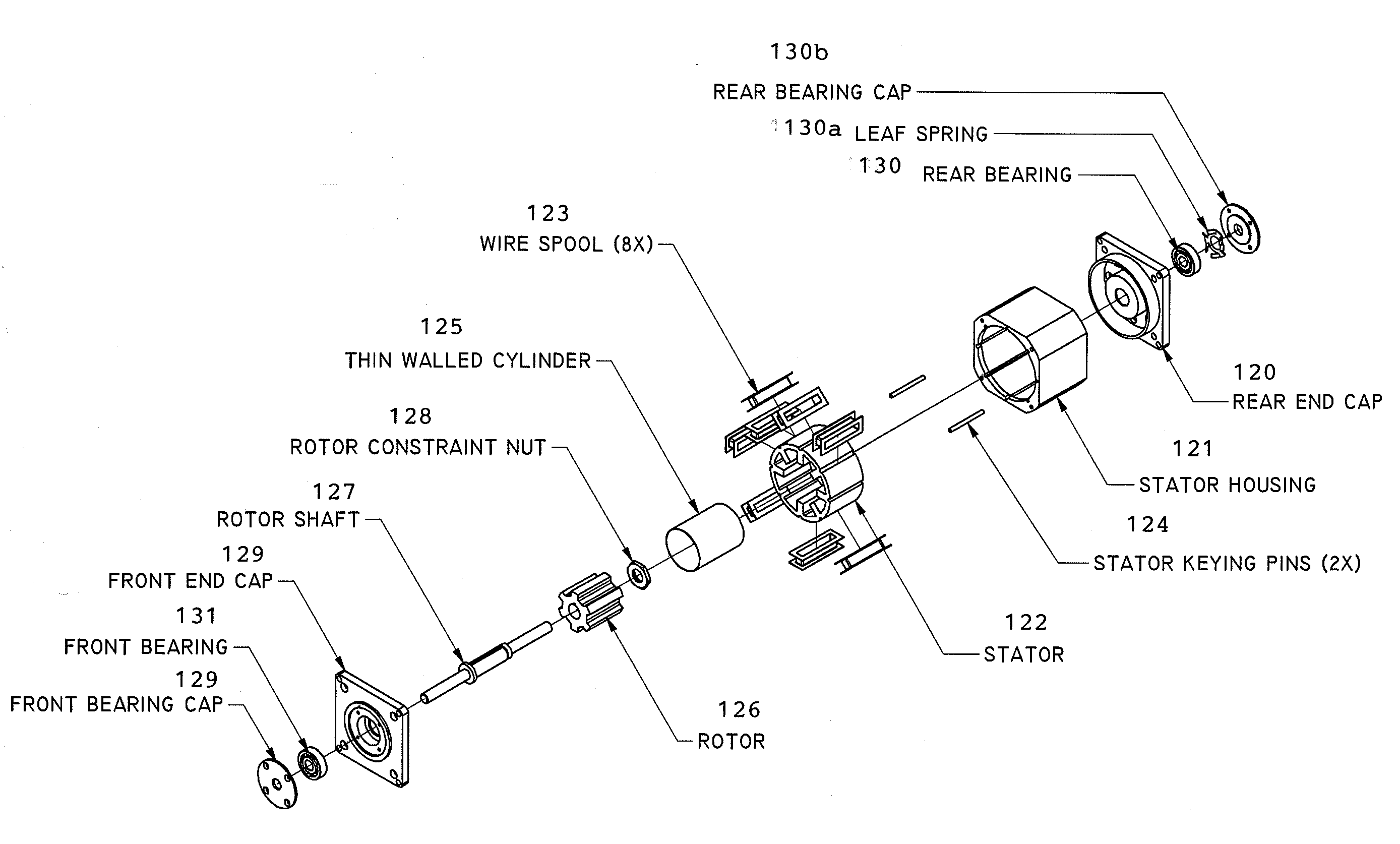
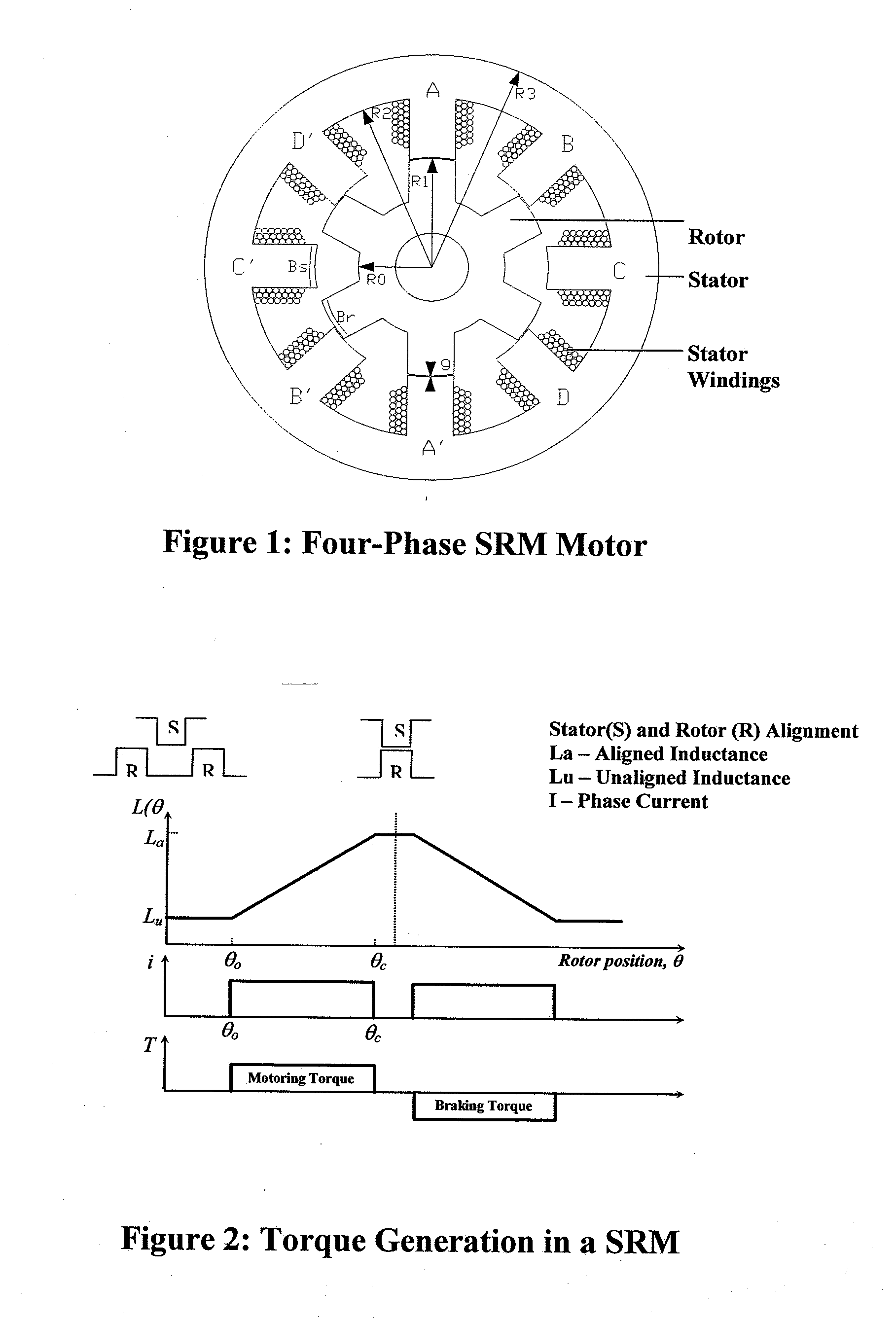
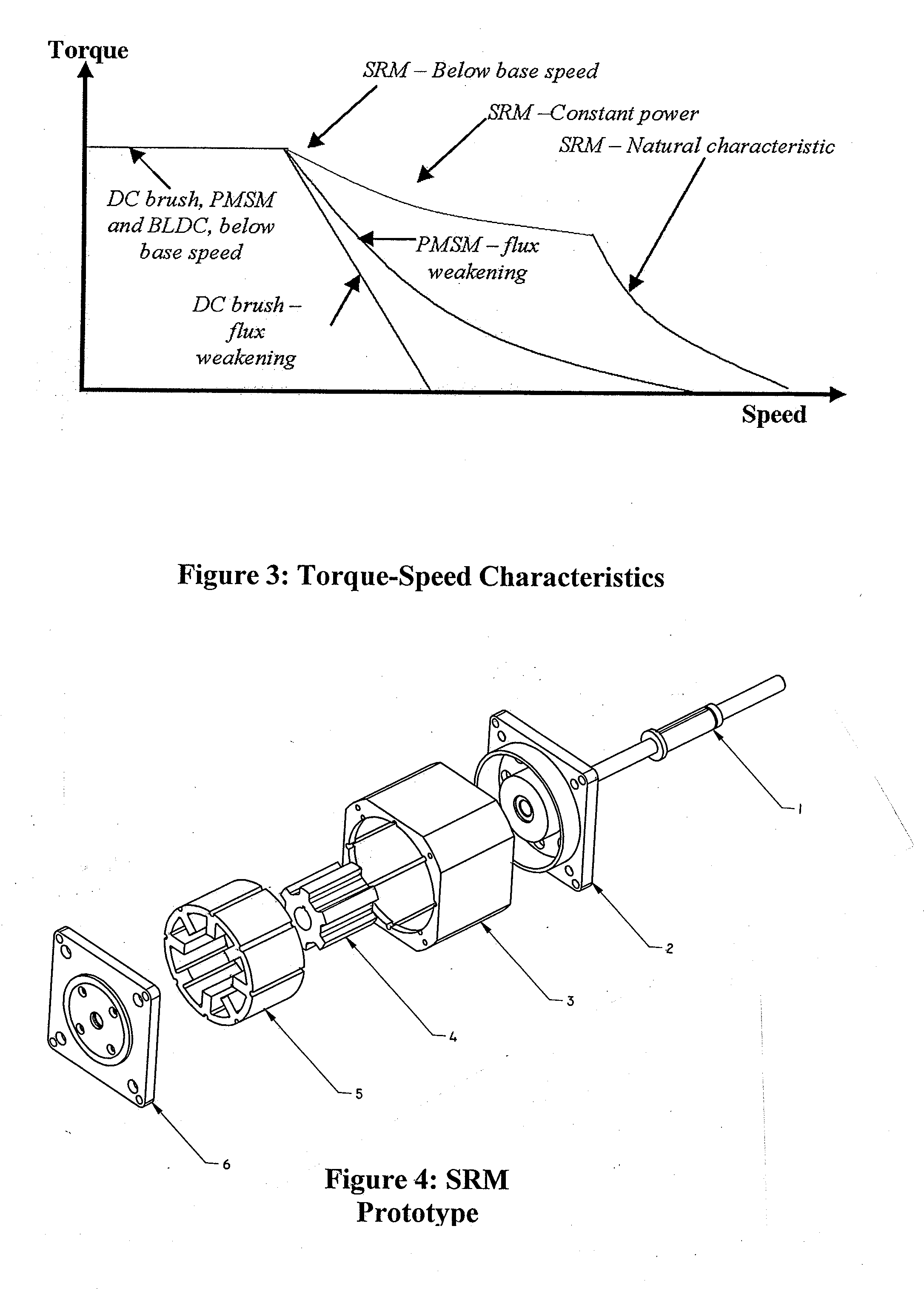
[0027]In a preferred embodiment, a switched reluctance motor (SRM) of doubly-salient, singly-excited type is used, with salient poles on both the rotor and stator, but only the stator carries windings, as shown in FIG. 1. The rotor has no windings, magnets, or cage winding. Both the rotor and the stator are built up from a stack of magnetic-alloy, salient-pole laminations. The purpose of the stacked laminations is to reduce eddy current losses during operation. The SRM employs electronic commutation, for which the magnetic field is stepped through the poles physically by sending current pulse sequences to the coils, so that the rotor follows this field. The o...


PUM


Abstract

A high temperature motor has a stator with poles formed by wire windings, and a rotor with magnetic poles on a rotor shaft positioned coaxially within the stator. The stator and rotor are built up from stacks of magnetic-alloy laminations. The stator windings are made of high temperature magnet wire insulated with a vitreous enamel film, and the wire windings are bonded together with ceramic binder. A thin-walled cylinder is positioned coaxially between the rotor and the stator to prevent debris from the stator windings from reaching the rotor. The stator windings are wound on wire spools made of ceramic, thereby avoiding need for mica insulation and epoxy / adhesive. The stator and rotor are encased in a stator housing with rear and front end caps, and rear and front bearings for the rotor shaft are mounted on external sides of the end caps to keep debris from the motor migrating into the bearings' races.

Description

[0001]This is a continuation-in-part of U.S. patent application Ser. No. 12 / 255,465 filed on Oct. 21, 2008, which claimed the priority of U.S. Provisional Patent Application 60 / 981,726, filed on Oct. 22, 2007.[0002]This invention was developed with funding under Contract No. NNG05CA55C with NASA, a U.S. Government agency, and the Government retains certain rights therein.TECHNICAL FIELD[0003]This disclosure is in the field of motors and actuators that can operate in high temperature environments for extended periods of time, and more particularly to high-temperature switched reluctance and BLDC motors.BACKGROUND[0004]Most existing motors and actuators are not designed to survive in harsh high temperature environments. For example, an extraterrestrial sampling probe to be used in the environment of Venus would need to be operated with motors that can survive in temperatures of 460° C., pressures of 90 bar, and an atmospheric environment of CO2 gas for extended periods of time. There ...

Claims


Application Information

Patent Timeline
Patent Type & Authority Applications(United States)
IPC IPC(8): H02K3/30H02K37/02H02K5/16H02K3/34
CPCH02K1/02H02K3/522H02K5/128H02K3/50H02K21/14H02K37/04H02K37/14H02K19/06
Inventor ROOPNARINE,
Owner HONEYBEE ROBOTICS
Why Eureka
Try Eureka