Use of fiber optic sensor techniques for monitoring and diagnostics of large AC generators

a technology of fiber optic sensor and large ac generator, which is applied in the direction of optical radiation measurement, cathode-ray oscilloscope, instruments, etc., can solve the problems of unsuitable and unsuitable rayleigh distributive fiber optic system, and achieve the effect of improving the vibratory analysis efficiency and reducing the cost of operation

Active Publication Date: 2012-02-02
INNOVATIVE DIAGNOSTIC SYST
View PDF8 Cites 54 Cited by
  • Summary
  • Abstract
  • Description
  • Claims
  • Application Information

AI Technical Summary

Benefits of technology

[0009]The invention described herein enables the operator of an electric generator to monitor the condition of the stator core and winding portion within the generator stator core. A second feature of the invention enables the operator to monitor the temperature of all electric connectors, such as phase connections, series connections, main lead connections, i.e., all the mechanical connectors which are always found beyond the region of the stator core. The winding itself between these connections can also be monitored for temperature and mechanical strain. All measurements within the scope of this invention are to be made with distributed fiber optic sensors, which can be a series of Fiber Bragg gratings, Rayleigh backscattering sensors and / or Brillouin frequency shift sensors, the selection of the appropriate method, where it possible to specify, is enumerated herein. It must be noted that the Fiber Bragg grating with wave length multiplexing would only be considered for the stator core tightness measurement. All other measurements would be done with either the Rayleigh back-scattering or the Brillouin frequency shift analysis. A special application of Ramon temperature fiber optic back-scattering sensing is also proposed. All fiber optic sensors and the fiber optic cables associated with said sensors are designed and of sufficient sensing length to exit through the machine frame and be gathered as a grouping into a small sealed box (with removable cover), hereafter referred to as the “fiber box”, located appropriately on the outside of the machine, where all optical fibers can then be grouped and connected to the appropriate fiber optic sensor analyzer, whether it be for dense packed Fiber Bragg Grating cable(s), Rayleigh back-scattering sensing cable(s), Brillouin frequency shift sensing cable(s), or Raman distributive temperature sensing cable(s). Furthermore, the various fiber optic sensor laser analyzers may be intermittently connected as needed to the appropriate fiber optic cable located within the fiber box, or they may connect to a standoff fiber optic cable that enables the fiber optic sensor laser analyzer to be located in the control room of electric generator. Whether measured at the generator, in the control room, or via the interne to a remote site, fiber run configurations within the generator can be changed and reconfigured within the temporarily open but also sealable fiber box. This reconfiguration is necessary to take advantage of different spatial resolutions and variations in dynamic and static capabilities in association with different Rayleigh, Brillouin, or Raman distributive fiber optic sensor laser systems that might be employed as needed. Wherever, the various fiber optic sensor analyzers are located, the choice of intermittent vs. continuous “on-line” fiber optic sensor measurement and analysis would then be decided as needed, based both on machine history in the case of a retrofit of various fiber optic sensor options and / or on the amount of protection desired for the particular electric generator. For example, a large electric generator as might be found at a nuclear plant might be best served by continuous “on-line” fiber optic sensor measurement in view of the enormous economic consequences of a forced outage, which might necessitate all the options described herein in addition to those made available and fully described in U.S. patent Ser. No. 12 / 209,333, as the fiber optic sensor invention described herein is a direct augmentation to the capabilities of that US patent.

Problems solved by technology

The Rayleigh distributive fiber optic system is not currently capable of vibratory analysis, but that additional capability is under development by Luna Innovations of Blacksburg, Va.
(Other Rayleigh fiber optic sensors systems have a reach in the 2 kilometer range but these have larger numbers for the minimum spatial resolutions and are, therefore, not suitable for the top ripple spring measurement associated with stator coil tightness.)

Method used


Image

  • Use of fiber optic sensor techniques for monitoring and diagnostics of large AC generators
  • Use of fiber optic sensor techniques for monitoring and diagnostics of large AC generators
  • Use of fiber optic sensor techniques for monitoring and diagnostics of large AC generators

Examples


Embodiment Construction

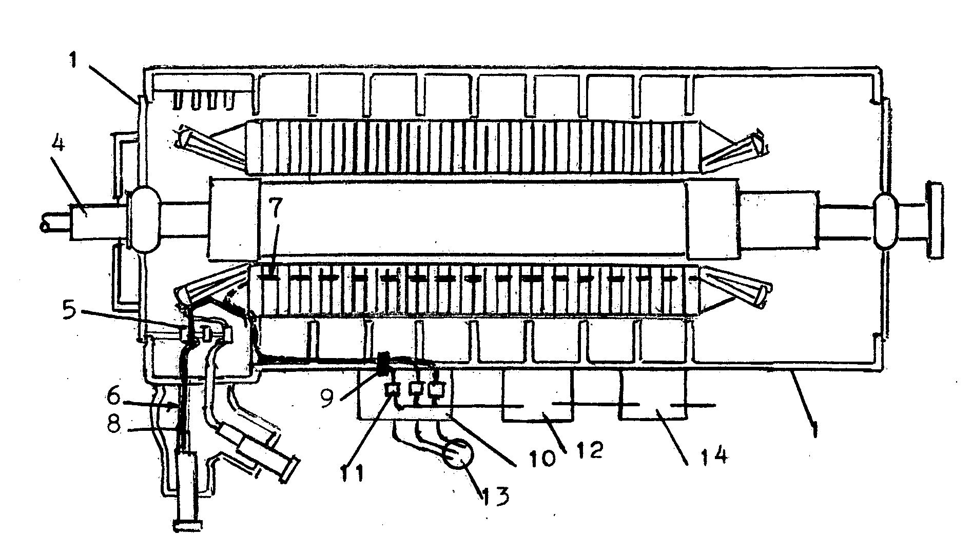
[0028]The following inclusive description of the preferred embodiment is made with reference to the above listed drawings. It should be noted that the preferred embodiment is somewhat different for a new factory machine versus field rewound units or field units that undergo only a re-wedge (stator coil tightening procedure). Obviously, in each case the amount and location of fiber optic cable that can be installed is somewhat different but does not detract from the spirit and scope of the current invention.

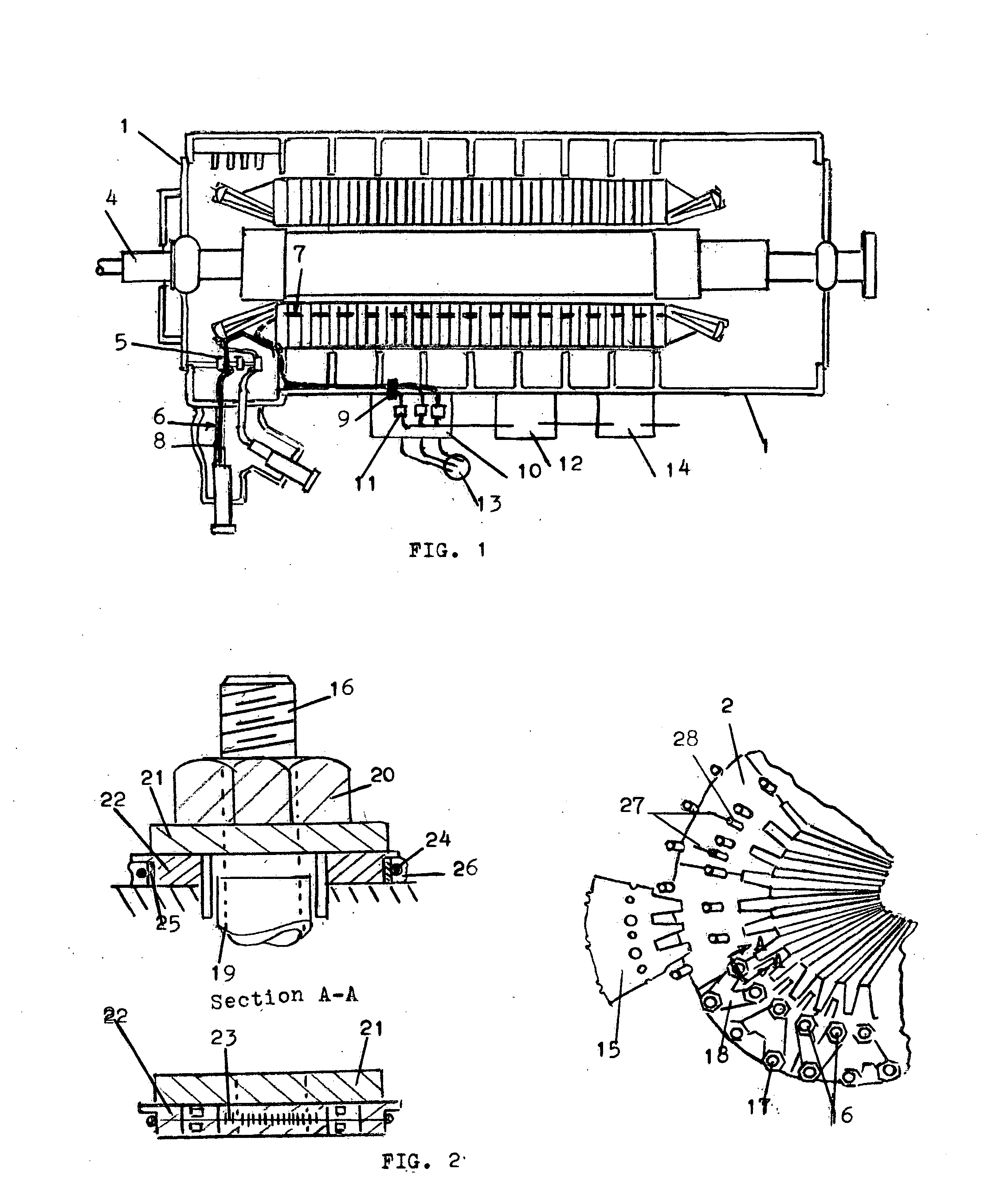
[0029]FIG. 1 shows a typical AC electric generator including the frame 1 within which is contained the stator core 2 integral electrically conductive windings showing the end regions 3 and rotor 4 Also enumerated in FIG. 1 are the parallel rings 5 which are connected to the main leads (typically six (6)) in number 6. Other key generator components are enumerated in subsequent figures. Attention is called to features of the invention described herein and further described below to ...


PUM


Abstract

A method for monitoring the operating conditions of an electric generator including the entire stator core and all winding components for conditions of mechanical strain and temperature throughout the machine by means of distributive fiber optic sensors based on both Rayleigh back scattering techniques and Brillouin frequency shift fiber optic sensor analysis both of which do not have the gaps and limitations associated with standard fiber Bragg grating fiber optic point sensors, by virtue of the fact that both Rayleigh and Brillouin scans and allow accurate strain and temperature determinations at all points along standard fiber optic cables of considerable length, approximately two kilometers in the case of the Brillouin, which effectively yields many tens of thousands of sensors throughout the entire standard fiber optic cable. Raman distributive temperature sensing also has a limited application. Single mode and polarizing maintaining fibers can both be analyzed and read with any Rayleigh or Brillouin distributive fiber optic sensor laser system allowing great flexibility in sensor spatial resolution, total sensed length, resolution and other factors not possible with conventional fiber Bragg gratings. A sealed fiber collection box located outside the electric generator permits enhanced reliability and reconfiguration into any number of desirable fiber layouts necessary for specific static and dynamic measurements in an optimal manner.

Description

CROSS REFERENCE TO RELATED APPLICATIONS[0001]This application claims the benefit under 35 U.S.C. 119(e) of U.S. Provisional Application No. 61 / 341 / 794 filed Apr. 5, 2010.FIELD OF THE INVENTION[0002]This invention relates generally to the monitoring of an electrical machine, specifically to a method and system for monitoring the magnetic stator core and portion of the windings within the magnetic stator core by means of distributed fiber optic sensor measurements through a collection of fiber optic cables in order to monitor the stator core and the electrical windings within and extending from the stator core.BACKGROUND OF THE INVENTION[0003]An electrical generator used in the field of electric power generation includes a stator core formed by an overlapping stack of thin electrical grade sheets of iron (laminations) which are coated with suitable insulation to electrically insulate each lamination from contiguous laminations. These laminations when properly stacked and aligned are t...

Claims


Application Information

Patent Timeline
Patent Type & Authority Applications(United States)
IPC IPC(8): G01J5/48
CPCG01D5/35303G01D5/35358G01L1/242G01K13/08G01K13/10G01K11/32
Inventor DAILEY, GEORGE FRANKLIN
Owner INNOVATIVE DIAGNOSTIC SYST
Why Eureka
Try Eureka