System for in vitro analysis of fluid dynamics on contact lenses via phase shifting interferometry

a technology of fluid dynamics and phase shifting interferometry, which is applied in the field of optical metrology, can solve the problems of reducing visual acuity along with discomfort, refraction errors, and turbulent tear film in places,

a technology of fluid dynamics and phase shifting interferometry, which is applied in the field of optical metrology, can solve the problems of reducing visual acuity along with discomfort, refraction errors, and turbulent tear film in places,

US20120026506A1Inactive Publication Date: 2012-02-02JOHNSON & JOHNSON VISION CARE INC

Image

  • System for in vitro analysis of fluid dynamics on contact lenses via phase shifting interferometry
  • System for in vitro analysis of fluid dynamics on contact lenses via phase shifting interferometry
  • System for in vitro analysis of fluid dynamics on contact lenses via phase shifting interferometry

Examples


Embodiment Construction

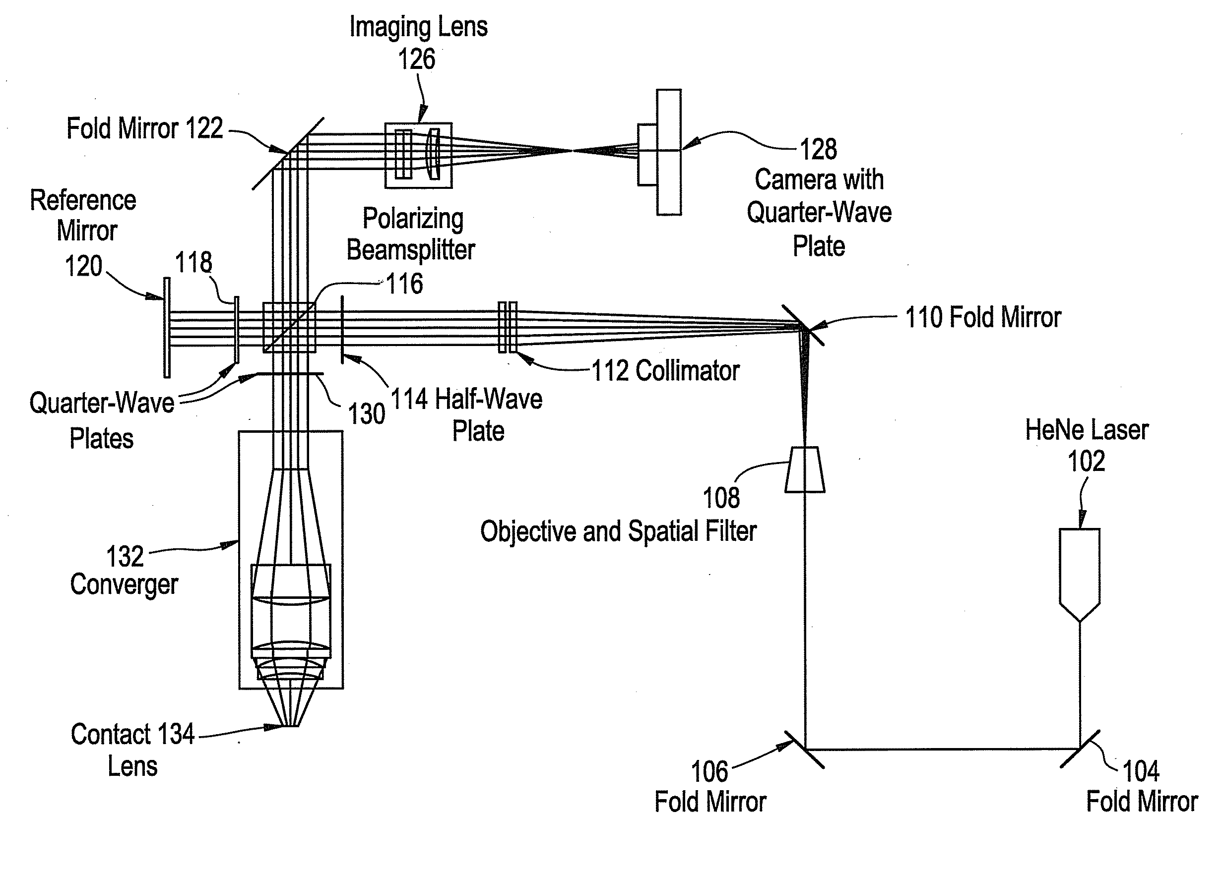
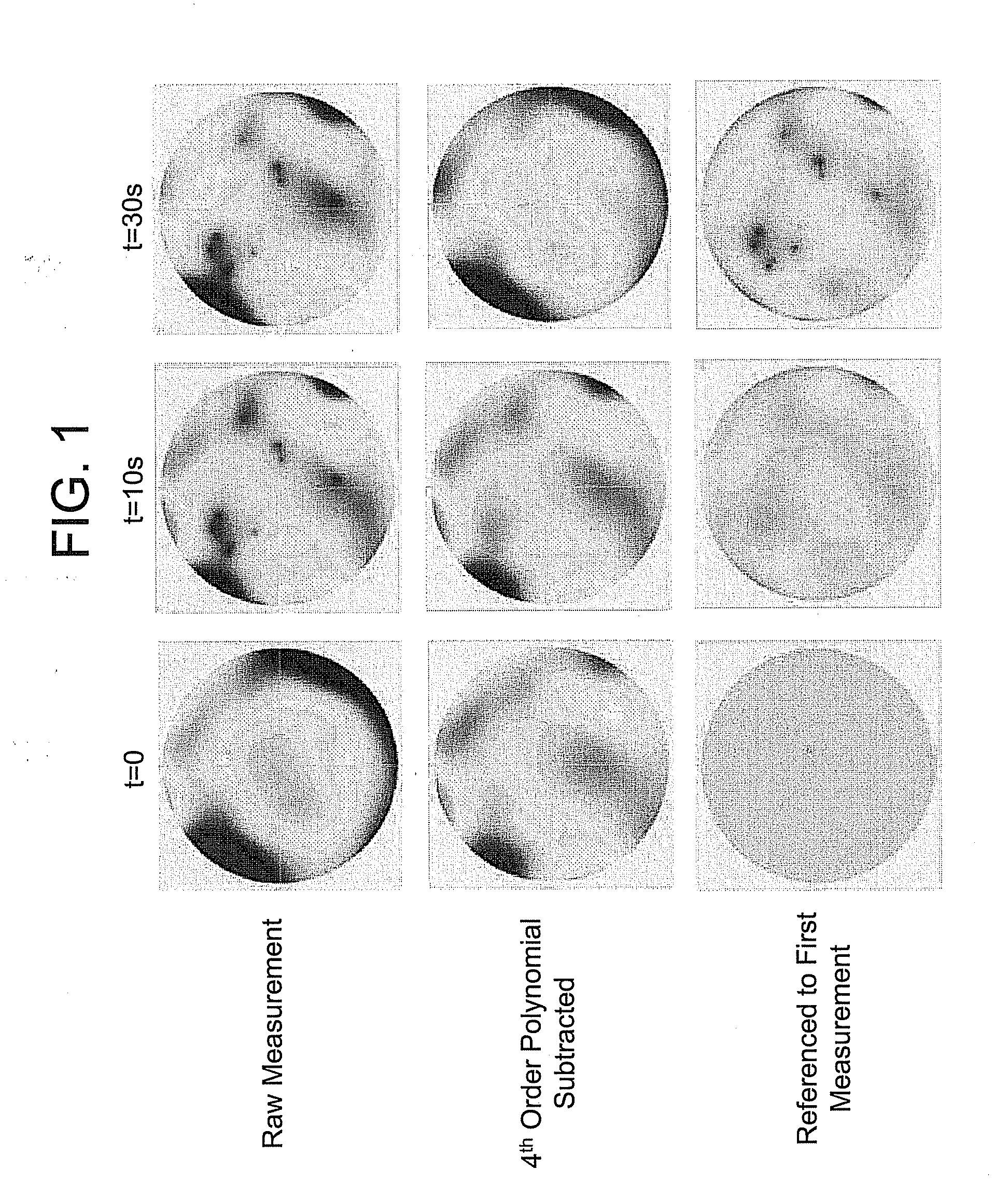
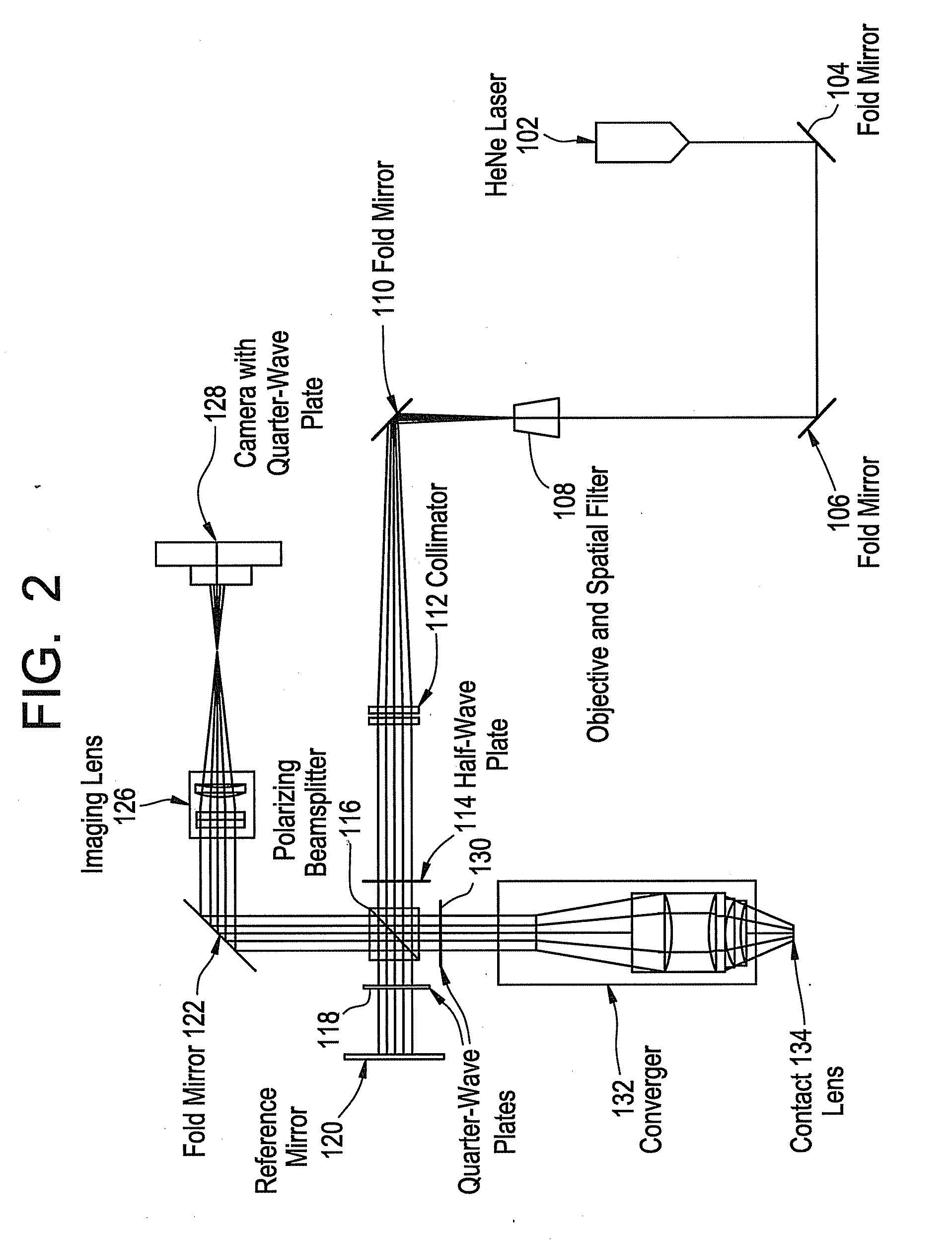
[0027]The in vitro system of the present invention uses phase shifting interferometry to measure the dynamics of fluid layers on contact lenses. The in vitro system measures the phase of a wavefront reflected from the fluid layer and uses this information to calculate its topographic surface profile. Such a system provides superior sensitivity and accuracy as well as better spatial resolution compared with static interferometers and can measure dynamic surfaces. Static interferometry relies on tracing the fringe centers of a single interferogram and has lower spatial sampling and lateral resolution than the phase shifting method. Additionally, static interferometry requires additional information to determine the proper wavefront orientation. In the present invention, in addition to superior accuracy, sensitivity and spatial resolution, higher speed is also achieved. Prior shearing methodologies were fast, but lacked sensitivity and spatial resolution to detect artifacts in the tear...


PUM


Abstract

A system and method for analyzing the dynamics of fluid layers on contact lenses utilizes phase shifting interferometry to quickly and accurately model the time-evolution of the fluid layers. The system and method are utilized for in vitro studies.

Description

CROSS-REFERENCE TO RELATED APPLICATIONS[0001]This patent application claims the benefit of U.S. Provisional Application No. 61 / 400,798 filed Aug. 2, 2010.BACKGROUND OF THE INVENTION[0002]1. Field of the Invention[0003]The present invention is directed to optical metrology, and more particularly to a system for measuring the dynamics and material interaction of fluid layers on contact lenses in vitro using phase shifting interferometry.[0004]2. Discussion of the Related Art[0005]In the human eye, the tear film is distributed over the cornea to create a smooth surface. Since the largest refractive index difference in the eye occurs at the air-to-tear film interface, this surface contributes a majority of the eye's optical power. In addition to its optical properties, the tear film serves to lubricate the eye, and in general keep it in a healthy state.[0006]When a person blinks, a new tear film is distributed on the cornea. After the blink, the tear film stabilizes. At this point in ti...

Claims


Application Information

Patent Timeline
02 Feb 2012
Publication
US20120026506A1
IPC
G01B9/02; G01B11/02
CPC
G01B11/2441; G01B2290/70; G01B9/02039
Inventors
PRIMEAU, BRIAN C.; GREIVENKAMP, JR., JOHN E.