Network terminal, network system, time synchronization method, and time synchronization program

Active Publication Date: 2012-02-02
THE UNIV OF TOKYO +1
View PDF2 Cites 11 Cited by
  • Summary
  • Abstract
  • Description
  • Claims
  • Application Information

AI Technical Summary

Benefits of technology

[0023]According to one or more embodiments of the present invention, scale of a network system can be suppressed. Further

Problems solved by technology

According to the RBS, however, a time synchronization server is required to broadcast-transmit a “reference packet” at regular intervals, resulting in expansio

Method used


Image

  • Network terminal, network system, time synchronization method, and time synchronization program
  • Network terminal, network system, time synchronization method, and time synchronization program
  • Network terminal, network system, time synchronization method, and time synchronization program

Examples


Example

[0045]The following describes embodiments of the present invention. In embodiments of the invention, numerous specific details are set forth in order to provide a more thorough understanding of the invention. However, it will be apparent to one of ordinary skill in the art that the invention may be practiced without these specific details. In other instances, well-known features have not been described in detail to avoid obscuring the invention.

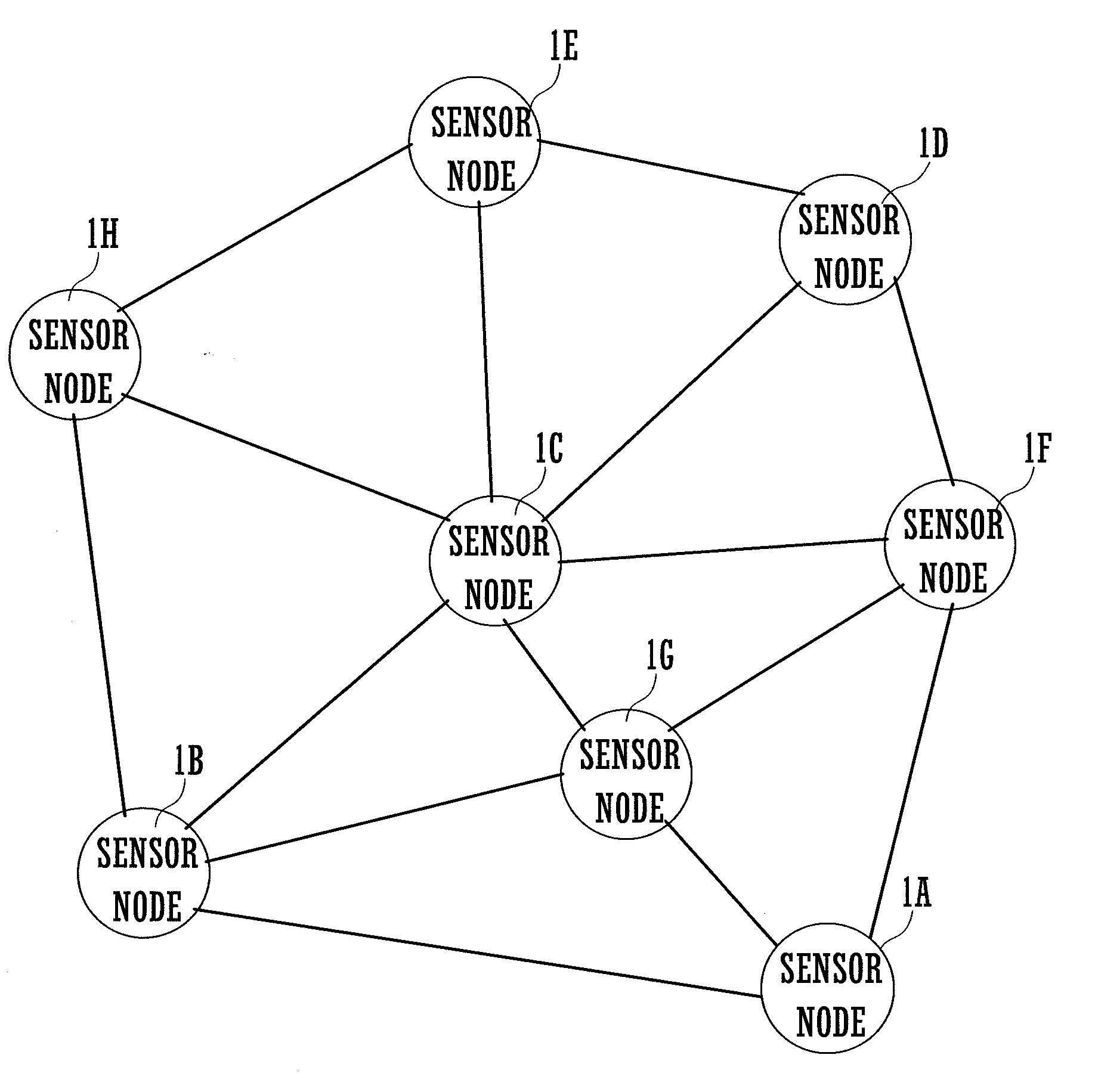
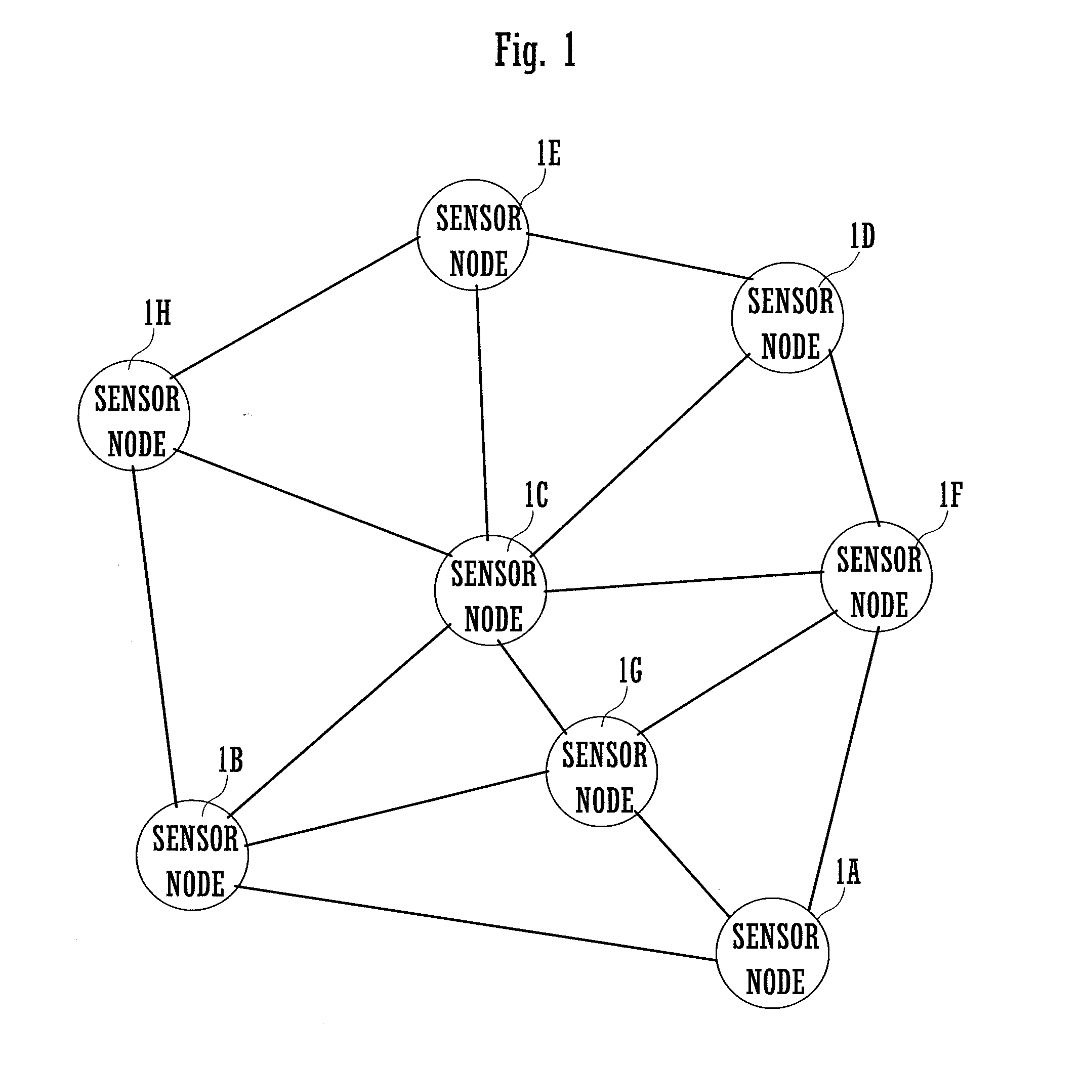
[0046]FIG. 1 illustrates a sensor network system. This sensor network system connects a plurality of sensor nodes 1 (1A to 1H) in a communicable manner via a network. In FIG. 1, lines connecting the sensor nodes 1 indicate links. These sensor nodes 1 correspond to network terminals referred to in one or more embodiments of the present invention. Communication between the sensor nodes 1 is performed directly or via another sensor node 1. In this specification, a directly communicable sensor node 1 may be called an adjacent sensor node 1, and a...


PUM


Abstract

A network terminal has communication section that communicates with other network terminals connected via a network, time-series data creation section that, at timing set beforehand, creates time information including a correspondence between an identification number of the own network terminal and a current time measured by a timer of the own network terminal and creates time-series data registering the time information, and additional registration section that, when the communication section receives the time-series data transmitted from another network terminal, creates time information including a correspondence between the identification number of the own network terminal and a current time measured by the timer of the own network terminal and additionally registers the time information to the time-series data received this time.

Description

BACKGROUND[0001]1. Technical Field[0002]The present invention relates to network terminals connected communicable with other network terminals via a network, network systems connecting a plurality of network terminals in a communicable manner via a network and time synchronization methods and time synchronization programs for synchronizing network terminals making up such a network system.[0003]2. Background Art[0004]Conventionally sensor network systems enabling mutual communication of a plurality of sensor nodes via a network have been used for the purposes such as hydrographic observation and seismic observation. A sensor node is disposed at each observation point. The sensor nodes are terminals equipped with a sensor function for measurement of phenomena to be observed and a communication function for communication with other sensor nodes. Then, measurement data by each sensor node is collected and processed for observation of a target.[0005]Such a sensor network system is requi...

Claims


Application Information

Patent Timeline
IPC IPC(8): H04J3/06
CPCG01V1/22G01V2200/12G06F1/14G04G7/00G04G5/00
Inventor NAITO, TAKESHIKAMIJO, SHUNSUKEFUJIMURA, KAICHI
Owner THE UNIV OF TOKYO
Why Eureka
Try Eureka