Light guiding bend with curved slits

Inactive Publication Date: 2012-02-02
TP VISION HLDG B V HOLDCO
View PDF5 Cites 9 Cited by
  • Summary
  • Abstract
  • Description
  • Claims
  • Application Information

AI Technical Summary

Benefits of technology

[0007]Hence, an improved light guide which with reduced light losses is able to transport light over sharp corners would be advantageous and in partic

Problems solved by technology

However, efficient internal reflections of the light guided at the slit surface occurs only at small angles, and hence eff

Method used


Image

  • Light guiding bend with curved slits
  • Light guiding bend with curved slits
  • Light guiding bend with curved slits

Examples


Embodiment Construction

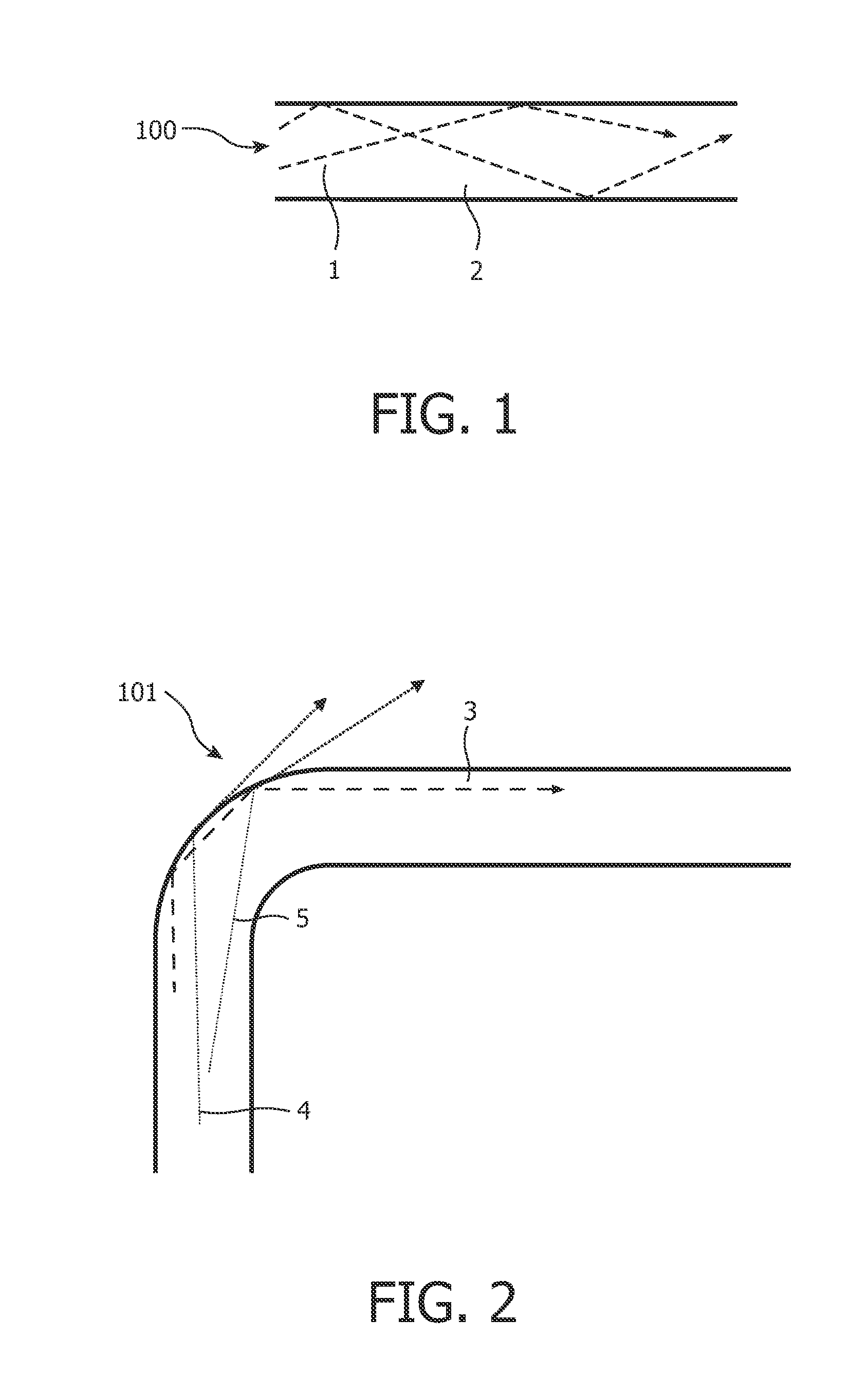
[0043]FIG. 1 is a schematic drawing representing the light path of a light ray which is guided in a light guide core, such as an optical fiber core. In general when a light ray hits a boundary between materials with different refractive indices, it is partially refracted at the boundary surface, and partially reflected. FIG. 1 shows a light guide core 100 where light ray 1 and 2 hit the light guide core boundaries with an angle of incidence which is greater (i.e. the ray is closer to being parallel to the boundary) than the critical angle for the boundary. As shown in FIG. 1 the light rays 1 and 2, as their angle of incidence is above the critical angle, experience total internal reflection so that effectively all the light of light rays 1 and 2 is reflected internally.

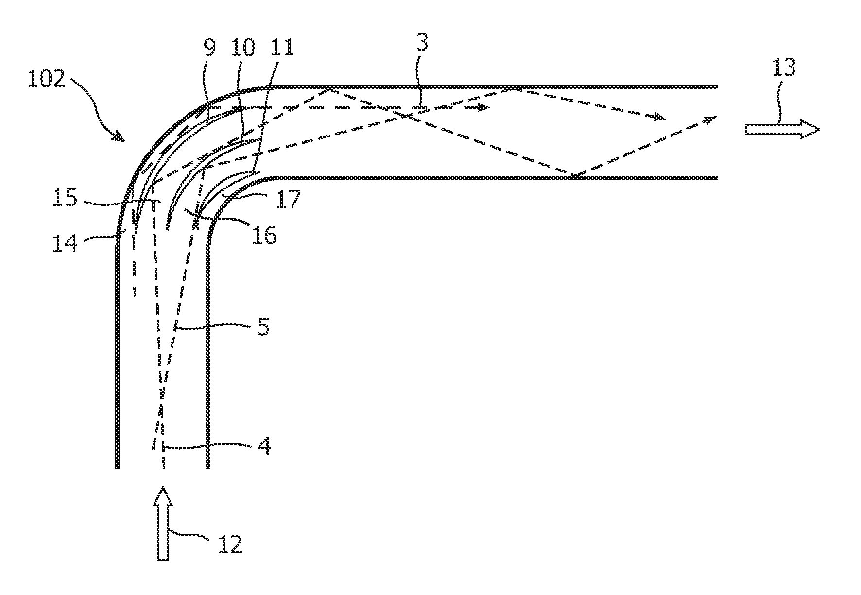
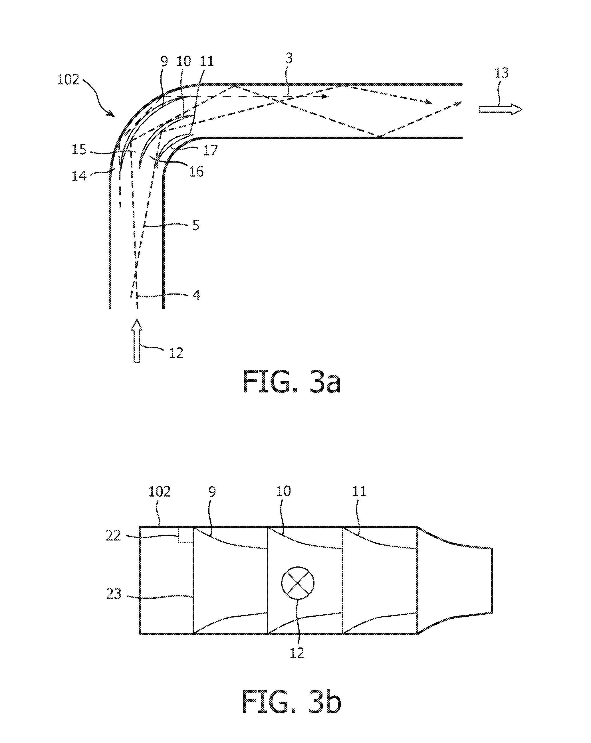
[0044]This is normally not the case when the light guide is bent as shown by FIG. 2. In a bent light guide 101 light ray 3, which hits the light guide core boundary with an angle of incidence above the critical angle,...


PUM


Abstract

A light guide (102) for bending guided light from a first direction (12) into a second direction (13) using a set of curved slits (9, 10, 11) formed in the light guiding core. The set of curved slits delimits separate bent light guide channels (14, 15, 16, 17) which guide the light through the bent light guide channels by total internal reflection.

Description

FIELD OF THE INVENTION[0001]The present invention relates to the field of light guiding, and more specifically to a light guide with reduced light losses.BACKGROUND OF THE INVENTION[0002]Light guides are used in many lighting applications, such as for general lighting purpose as well as backlight sources for Liquid Crystal Display (LCD) or TV screens.[0003]This type of construction is generally used for back-light illumination of, e.g. LCD monitors, where a source of light is connected to one side of the light guide plate and the light is reflected towards the LCD, by means of reflecting structures.[0004]Another possible application in which light guides can be used is for example background lightning for television sets, such as flat screen display panel. Light effects generated around a display panel may be guided from a single point source, for example an LED or a laser beam, over the perimeter of the display panel. In this way a large area can be illuminated by using a limited a...

Claims


Application Information

Patent Timeline
IPC IPC(8): G02B6/26G02B6/125
CPCG02B2006/12119G02B6/125
Inventor KRIJN, MARCELLINUS PETRUS CAROLUS MICHAELSALTERS, BART ANDRE
Owner TP VISION HLDG B V HOLDCO
Why Eureka
Try Eureka