Base Station and Cellular Wireless Communication System

a cellular wireless communication system and base station technology, applied in substation equipment, power management, wireless commuication services, etc., can solve problems such as full compensation, achieve high communication quality, reduce interference, and simplify hotspot installation in cellular wireless communication systems

Inactive Publication Date: 2012-02-02
HITACHI LTD
View PDF12 Cites 44 Cited by
  • Summary
  • Abstract
  • Description
  • Claims
  • Application Information

AI Technical Summary

Benefits of technology

[0033]The present invention is capable of providing control of transmit power in terminals while both minimizing the interference applied to neighboring cells and attaining high communication quality in its own cell during the uplink. The present invention can for example be effectively applied to femtocell base stations.
[0034]The improved easy installation of femtocell base stations has made hotspot installation simpler in cellular wireless communication systems, which is beneficial in terms of minimizing effects on the macrocell base station.

Problems solved by technology

However when the α falls below 1.0 the PL is not fully compensated, and the base station does not maintain the received power at an equal amount among the terminals.

Method used


Image

  • Base Station and Cellular Wireless Communication System
  • Base Station and Cellular Wireless Communication System
  • Base Station and Cellular Wireless Communication System

Examples


first embodiment

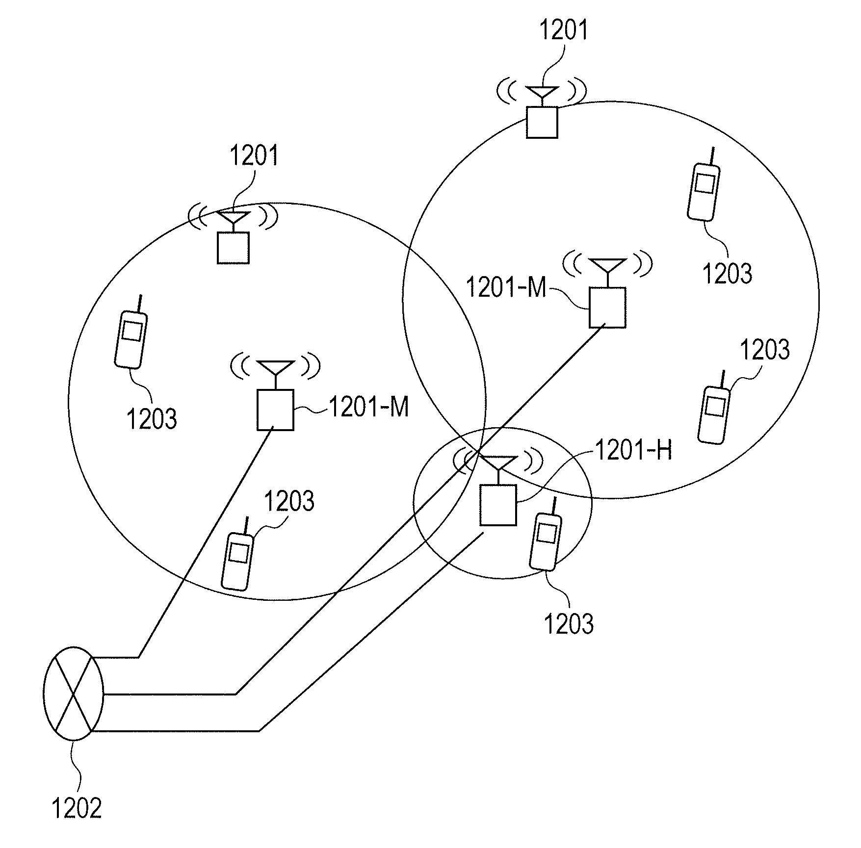
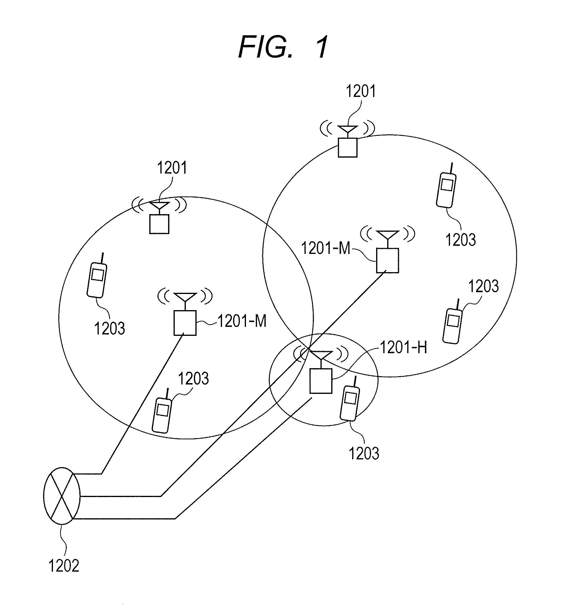
[0051]FIG. 1 describes the overall configuration of the cellular wireless communication system of the present embodiment.

[0052]The cellular wireless communication system of the present embodiment is comprised for example the macrocell base stations 1201-M and the femtocell base station 1201-H. The terminal 1203 can communicate with the macrocell base stations 1201-M and the femtocell base station 1201-H.

[0053]The base station 1201 provides communication among terminals 1203 located at separate positions, and data communication services between terminals and contents providers through a core network 1202 configured from host devices such as element management servers, mobility management elements, and gateways. Even among base stations however, the femtocell base station connects to the core network 1202 via ISP (Internet Service Provider) network.

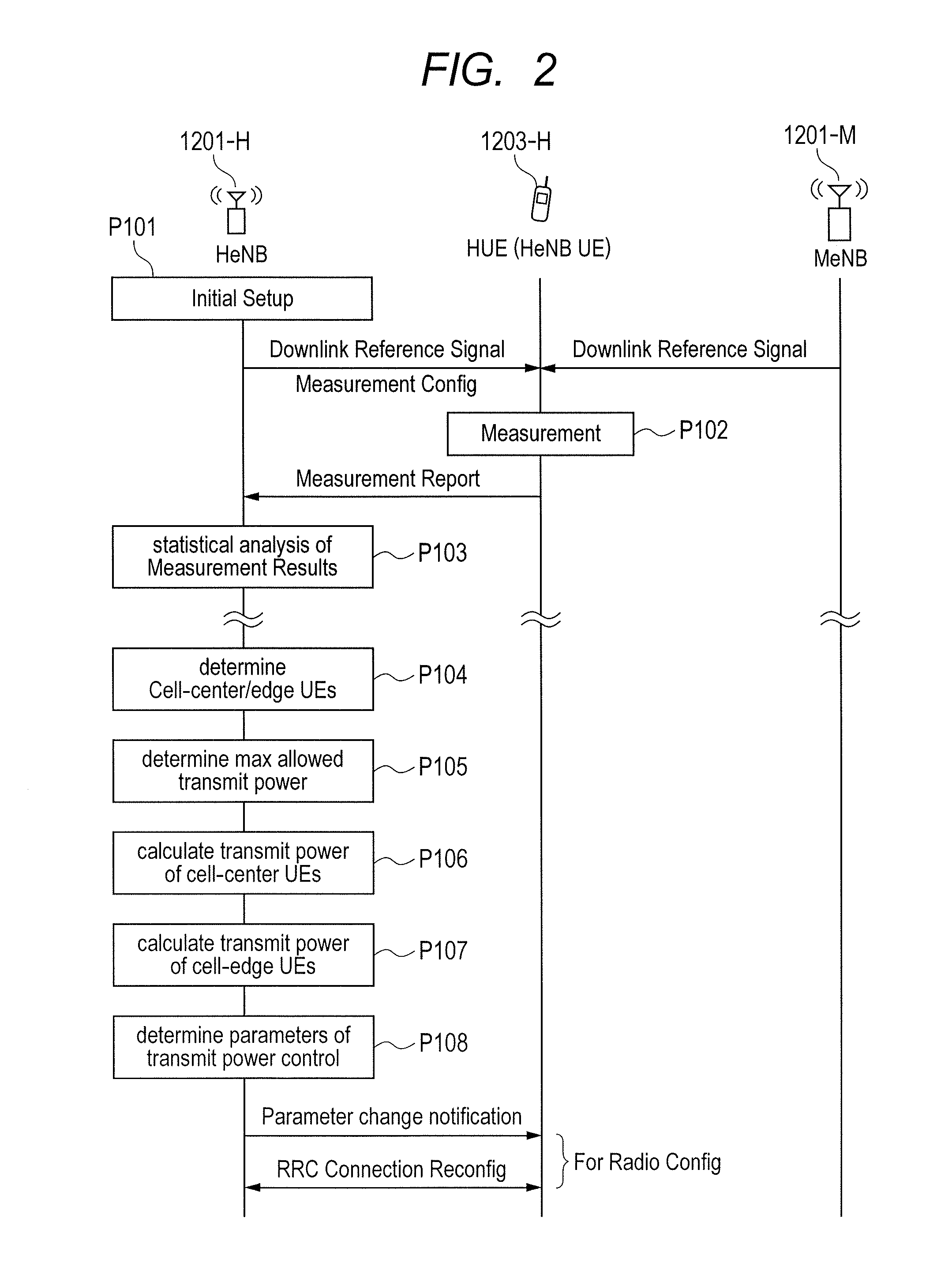
[0054]The operation of the present embodiment is described next utilizing the sequence shown in FIG. 2.

[0055]The femtocell base station 12...

second embodiment

[0083]The technique disclosed in the first embodiment is described next as a detailed method assuming usage is applied to LTE. The condition in P102 of FIG. 2 required for the terminal 1203-H to perform measurement, may be set as a value in the initial setup in P101, and notification made by using an RRC message.

[0084]The measurement scheme utilizes a function for reporting the RSRP (Reference Signal Received Power) or RSRQ (Reference Signal Received Power) or RSRQ (Reference Signal Received Quality). Reporting the RSRQ allows reporting in a format that is a power ratio of the RSSI (Received Signal Strength Indication) including the interference power of the reference signals from the other cells, and the received signal of its own cell. The report may be in the form of either the RSRP or the RSRQ, or a collection of both. However, usually one of these formats is used due to the possibility that numerous configuration rewrites will occur, and a training period then set, and other ma...

third embodiment

[0092]The first embodiment deals with the case in P107 where the maximum allowed transmit power of the cell-edge terminal is small. If the maximum allowed transmit power is small, then the estimated communication quality at the femtocell base station 1201-H will sometimes be worse than expected.

[0093]In this case, the problem can be resolved by implementing control linked to the cell-edge terminal scheduling method to lower the power density, or by increasing the allocation resources. In base stations such as femtocells that accommodate few individuals, allocating a large quantity of resources is an easy to employ avoidance method.

[0094]In wireless communication systems such as LTE for example, resources can be allocated along the time axis and along the frequency axis. The OFDMA / SC-FDMA schemes are multiplexing methods for allocating terminals to each resource.

[0095]When increasing resource allocation along the frequency axis, lowering the power density on each resource and increas...


PUM


Abstract

A femtocell base station collects the terminal distribution within the cell and selects terminals to represent the cell-center and the cell-edge from among the terminals within the cell. The femtocell base station also calculates maximum transmit power for the respective the cell-center and cell-edge terminals allowable by the macrocell base station. The femtocell base station sets the respective transmit power of the cell-center and the cell-edge in a range that will not exceed the maximum transmit power, adjusts the transmit power control parameter to allow control by the terminal at the power value that was set, and notifies the terminal. Communication with high throughput can in this way be attained for terminals in cells within the femtocell base station during uplink communications to the femtocell base station, and interference applied to the terminals in the macrocell base station can be suppressed.

Description

CLAIM OF PRIORITY[0001]The present application claims priority from Japanese patent application JP 2010-170242 filed on Jul. 29, 2010, the content of which is hereby incorporated by reference into this application.FIELD OF THE INVENTION[0002]The present invention relates to a base station and a cellular wireless communication system, and relates in particular to a base station and a cellular wireless communication system that makes uplink transmit power control settings while taking the applied interference into account. The present invention also relates to power control of terminals by base stations in cellular wireless communication system utilizing the orthogonal frequency division multiple access system (OFDMA).BACKGROUND OF THE INVENTION[0003]A typical configuration for a cellular wireless system is first of all described.[0004]Cellular wireless communication systems are comprised of communication areas called cells which are base stations {sometimes referred to as eNB (e-UTRA...

Claims


Application Information

Patent Timeline
Patent Type & Authority Applications(United States)
IPC IPC(8): H04W52/04H04W88/08
CPCH04W52/146H04W52/225H04W52/283H04W52/244H04W52/242
Inventor YAMAMOTO, TOMONORIKATAYAMA, RINTAROISHII, HIROTAKE
Owner HITACHI LTD
Why Eureka
Try Eureka