Cannula

a cannula and a technology of cannulas, applied in the field of cannulas, can solve the problems of obscuring the position of limited use of conventional cylindrical cannulas, and inability to accurately place the leading tip relative to the join

Inactive Publication Date: 2012-02-02
TUFTS MEDICAL CENTER INC
View PDF4 Cites 12 Cited by
  • Summary
  • Abstract
  • Description
  • Claims
  • Application Information

AI Technical Summary

Benefits of technology

[0008]Advantageously, since the peripheral shape of cannula has the form of a minor arc, the device provides an arcuately shaped, trough-like surface which receives and guides surgical instruments, and is not limited to instruments of any particular diameter. Also advantageously, by providing a fluid channel within the body of the cannula, waste irrigation fluid, blood, or tissue fragments can be removed from the vicinity of the leading tip of the cannula by drawing them into the fluid channel so as to permit clear visualization of the joint and the position of the device relative to the joint. Alternatively, the fluid channel can also be used to introduce irrigation fluids into the surgical field.

Problems solved by technology

Conventional cylindrical cannulas are limited to use with instruments having an outer diameter less than that of the inner diameter of the cannula.
Moreover, the leading tip of the cannula may be submerged in pooled body or irrigation fluids in the operative field whereby visualization of the joint, and position of the leading tip relative to the joint, is obscured.
In these situations, accurate placement of the leading tip relative to the joint, and ultimately, placement of the inserted instrument, can be difficult.

Method used


Image

  • Cannula
  • Cannula
  • Cannula

Examples


Embodiment Construction

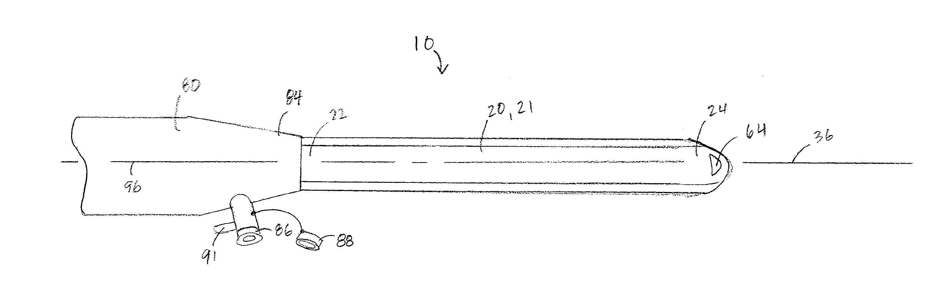
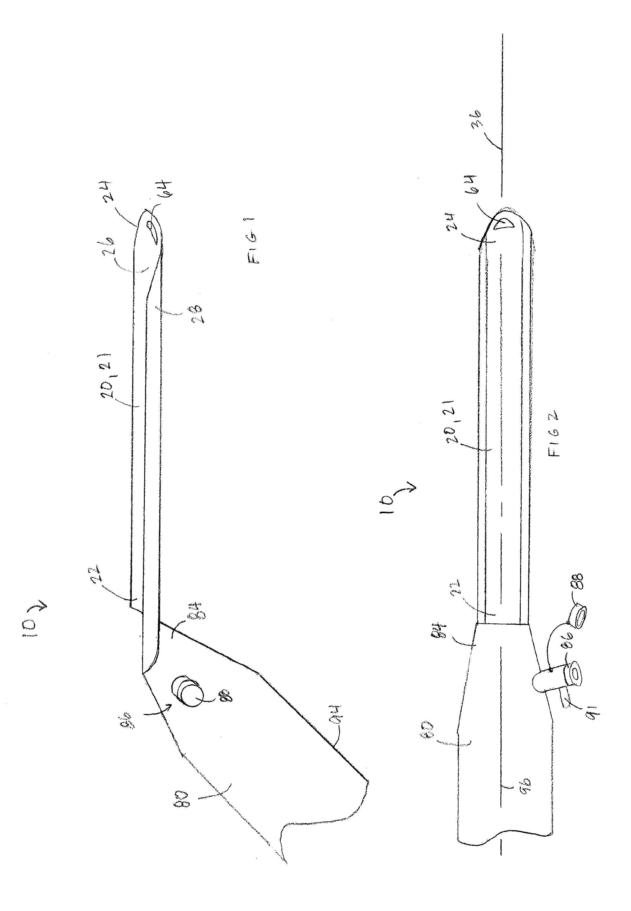
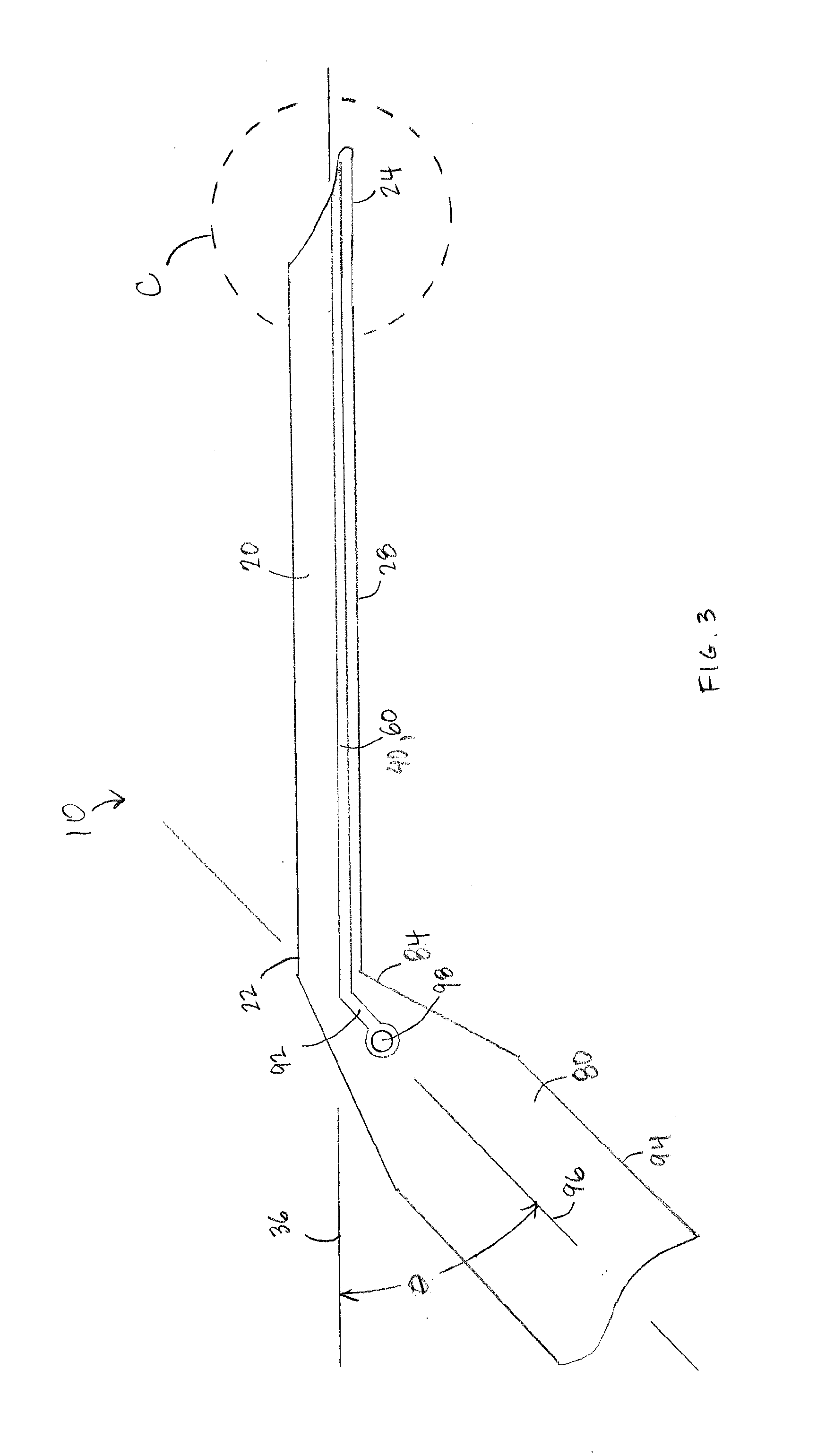
[0027]A device 10 for introducing surgical tools into a body will be described with reference to the figures. In the following description, references to orientations such as upper, upward, lower, downward, etc. are made for descriptive purposes with respect to the orientation of the device shown in FIG. 1 rather than to imply any absolute relative orientation.

[0028]Referring now to FIG. 1, the device 10 includes a slotted cannula 20 supported on a handle 80. The cannula 20 is an elongate plate 21 having a first end 22 rigidly connected to an end 84 of the handle 80. Elongate plate 21 is curved in the width direction so that the cannula 20 has a cross-sectional shape that is a minor arc opening upward. As a result of this configuration, the cannula 20 includes an upward-facing, concave tool receiving surface 26, and an opposed, downward-facing, convex outer surface 28. In some embodiments, the minor arc has a circumferential arc length in a range between 20 degrees and 180 degrees.

[...


PUM


Abstract

A device for introducing surgical tools into a body is provided that a slotted cannula supported on a handle. The cannula is an elongate plate having a first end rigidly connected to an end of the handle, and a second end opposed to the first end. The plate is curved in the width direction so that the cannula has a cross-sectional shape that is a minor arc opening upward. As a result of this configuration, the cannula has a concave tool receiving surface, and an opposed, convex outer surface. A cannula fluid channel is disposed between the tool-receiving and outer surfaces. The cannula fluid channel extends from the handle to the second end of the cannula, and opens to the cannula exterior at the leading tip of the cannula.

Description

CROSS REFERENCE TO RELATED APPLICATIONS[0001]This application claims the benefit of the priority U.S. Provisional Application 61 / 166,971, filed Apr. 6, 2009, the contents of which are incorporated herein by reference.BACKGROUND OF THE INVENTION[0002]1. Field of the Invention[0003]The present invention is related to surgical instruments and, more specifically is related to a cannula for use in arthroscopic procedures.[0004]2. Description of the Background Art[0005]It is well known to use specialized tools to aid insertion of surgical instruments such as arthroscopes, cutting and / or trimming tools, clamps, optical devices, etc. into a body for use during arthroscopic procedures in which movable joints are repaired, replaced or surgically constructed. For example, a cannula in the form of a rigid tube is often inserted into the body and used to direct the surgical instruments to a desired location in an operative field while minimizing trauma to surrounding tissue.[0006]Conventional cy...

Claims


Application Information

Patent Timeline
Patent Type & Authority Applications(United States)
IPC IPC(8): A61B1/32
CPCA61B17/3421A61M1/008A61B2217/005A61B2019/4889A61B2090/0817A61M1/84
Inventor SMITH, ERIC
Owner TUFTS MEDICAL CENTER INC
Why Eureka
Try Eureka