Wearable type movement assisting apparatus

a technology of assisting apparatus and wearable type, which is applied in the field of can solve the problems of difficult to move finger joints, difficult to transmit neural signals from the brain, and conventional wearable type movement assisting apparatus has a considerable amount of weight, so as to achieve efficient transmission of driving force and reduce the load of wearers

Active Publication Date: 2012-02-02
CYBERDYNE INC
View PDF6 Cites 109 Cited by
  • Summary
  • Abstract
  • Description
  • Claims
  • Application Information

AI Technical Summary

Benefits of technology

[0008]According to an aspect of the present invention, a driving force of a driving part allows a finger joint of a wearer to move by expanding or contracting a linear member in a movement direction of the finger joint in accordance with a drive control signal from a control part. Thereby, weight-reduction can be achieved. In addition, the load of the wearer can be reduced by efficiently transmitting the driving force of the driving part to a movement assisting glove.

Problems solved by technology

For example, there may be a case where it becomes difficult to transmit neural signals from the brain due to illness or injury or a case where it becomes difficult to move finger joints according to a one's intention due to deterioration of muscles or damage to one's tendons or ligaments provided at one's joints.
Thus, the conventional wearable type movement assisting apparatus has a considerable amount of weight and has a problem of imposing a large load on the wearer.
Although weight-reduction of the conventional wearable type movement assisting apparatus by reducing the size of the actuators is considered, there is a problem where torque cannot suffice for the weight of the movable parts made of many components.Patent Document 1: Japanese Laid-Open Patent Application No. 2002-345861

Method used


Image

  • Wearable type movement assisting apparatus
  • Wearable type movement assisting apparatus
  • Wearable type movement assisting apparatus

Examples


embodiment 1

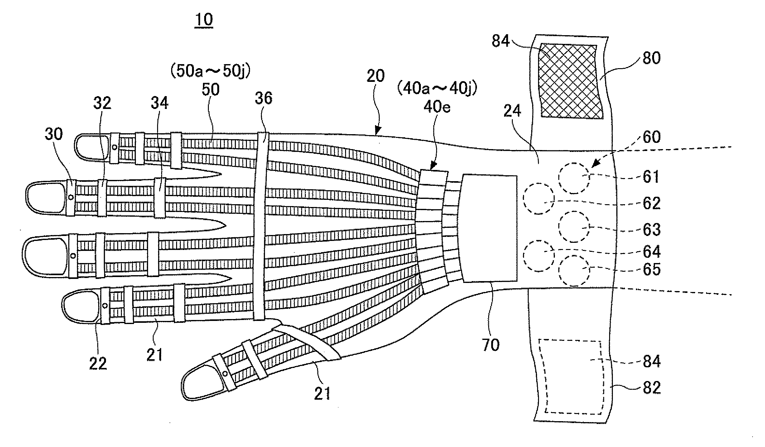
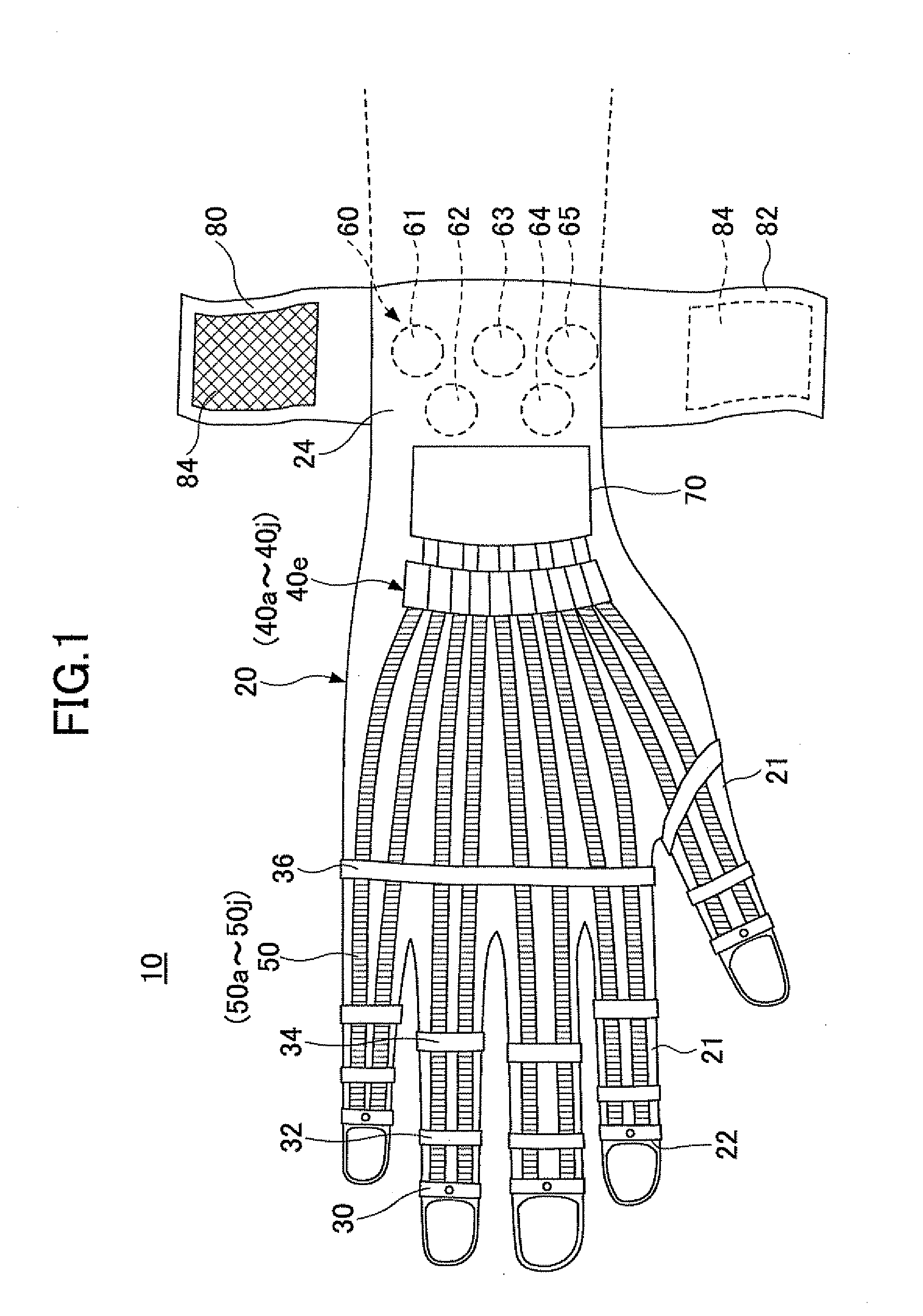
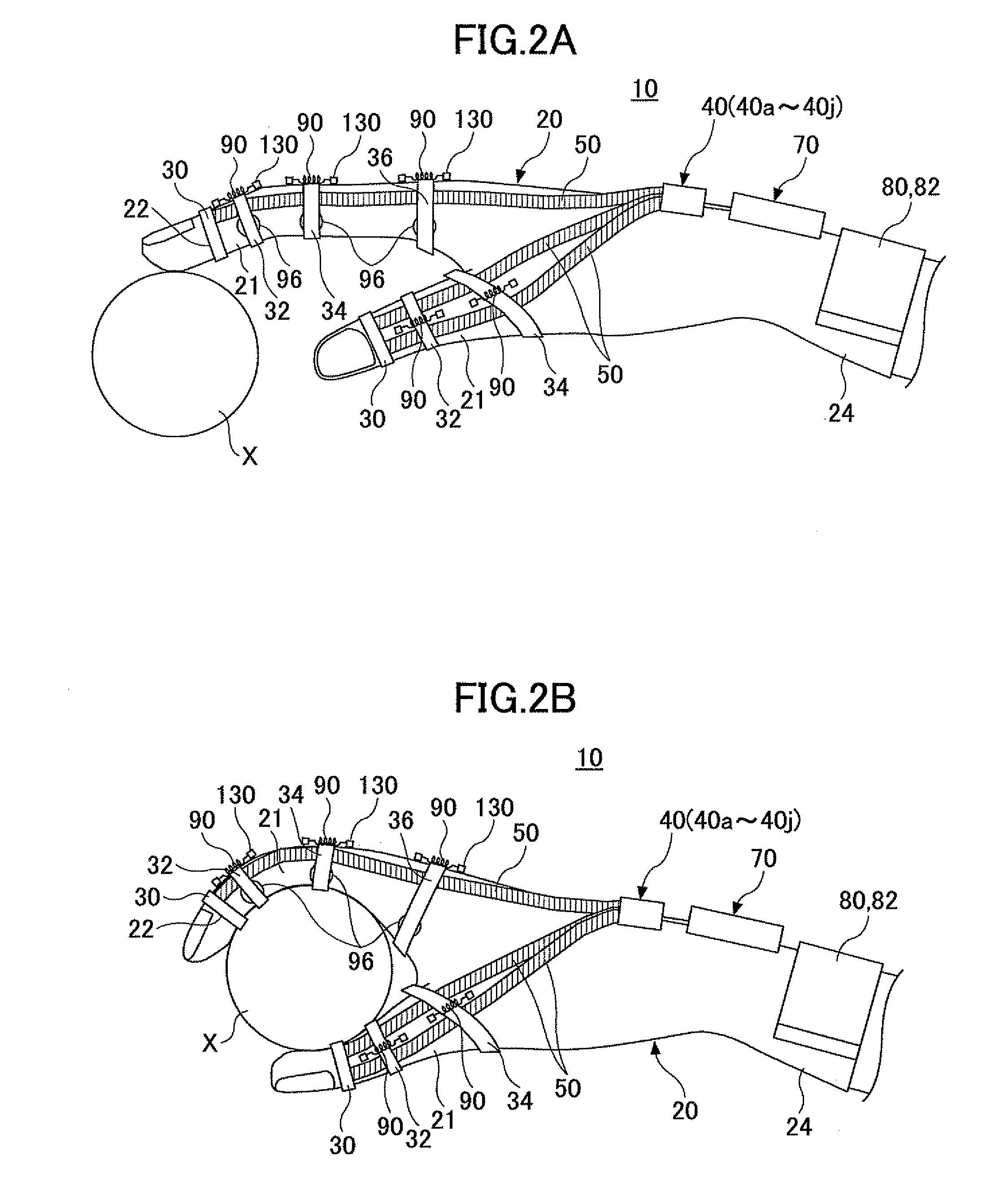
[0114]FIG. 1 is a plan view illustrating a wearable type movement assisting apparatus according to a first embodiment of the present invention. FIG. 2A is a side view of the wearable type movement assisting apparatus 10 according to the first embodiment of the present invention. FIG. 2B is a schematic diagram illustrating a movement state where an object X is grabbed by using the wearable type movement assisting apparatus 10 according to the first embodiment of the present invention. As illustrated in FIGS. 1 and 2A, the wearable type movement assisting apparatus 10 has a movement assisting glove 20 including finger insertion parts 21 into which each finger of the wearer is inserted. The movement assisting glove 20 is worn in a same manner as a typical glove. The movement assisting glove 20 includes a driven part 30, a driving part 40 (40a-40j), a linear member 50 (50a-50j), a biosignal detection part 60, and a control unit 70.

[0115]The wearable type movement assisting apparatus 10 ...

embodiment 2

[0168]FIG. 8 is a schematic diagram for describing a signal process of a control part 100B according to the second embodiment of the present invention. In the second embodiment, like components / elements are denoted with like reference numerals as those illustrated in FIG. 4 of the first embodiment and are not further described.

[0169]The control part 100B of the second embodiment illustrated in FIG. 8 includes the biopotential process part 200, the voluntary control part 212, a database 300, and the drive current generation part 220. Because the configuration of the movement assisting glove 20 of the second embodiment is the same as that of the first embodiment, the movement assisting glove 20 of the second embodiment is not further described. The control part 100B is an example of the control part 100 of FIG. 3.

[0170]The database 300 of the control part 100E obtains, for example, the rotation angles and the angular speed of each finger joint of the wearer corresponding to all phases...

embodiment 3

[0189]FIG. 12 is a schematic diagram for describing a signal process of a control part 1000 according to the third embodiment of the present invention. In the third embodiment, like components / elements are denoted with like reference numerals as those illustrated in FIGS. 5 and 8 of the first and second embodiments and are not further described.

[0190]The control part 100C of the third embodiment illustrated in FIG. 12 includes the biopotential process part 200, the voluntary control part 212, the database 300, an autonomous control part 310, a control signal compositing part 320, and the drive current generation part 220. Because the configuration of the movement assisting glove 20 of the third embodiment is the same as that of the first embodiment, the movement assisting glove 20 of the third embodiment is not further described. The control part 100C is an example of the control part 100 of FIG. 3.

[0191]The autonomous control part 310 estimates the task and phases of the wearer by ...


PUM


Abstract

A wearable type movement assisting apparatus includes a movement assisting glove including a finger insertion part into which a finger of a wearer is inserted, a driving part arranged on a backhand side of the movement assisting glove and configured to drive the finger insertion part, a linear member arranged along the finger insertion part and configured to transmit a driving force of the driving part to the finger insertion part, a biosignal detection part configured to detect a biosignal that causes the finger of the wearer to move, and a control part configured to output a drive control signal to the driving part based on the biosignal detected by the biosignal detection part. The driving part is configured to move the linear member in an extending direction or a bending direction of the finger insertion part based on the drive control signal from the control part.

Description

TECHNICAL FIELD[0001]The present invention relates to a wearable type movement assisting apparatus, for example, a wearable type movement assisting apparatus for assisting or substituting movement of finger joints.BACKGROUND ART[0002]For example, there may be a case where it becomes difficult to transmit neural signals from the brain due to illness or injury or a case where it becomes difficult to move finger joints according to a one's intention due to deterioration of muscles or damage to one's tendons or ligaments provided at one's joints. As a wearable type movement assisting apparatus for assisting movement of such finger joints, there is an apparatus including movable parts attached to each finger and actuators for driving each of the movable parts (see, for example, Patent Document 1).[0003]The conventional wearable type movement assisting apparatus, however, has many components and a sophisticated configuration due to a rotary mechanism being provided in correspondence with ...

Claims


Application Information

Patent Timeline
Patent Type & Authority Applications(United States)
IPC IPC(8): A61H1/02
CPCA61B5/04001A61H2230/605A61B5/04888A61B5/1121A61B5/1125A61B5/6806A61B5/6812A61F2/72A61F5/013A61F2002/7625A61F2002/7635A61F2005/0188A61H1/0285A61H1/0288A61H2201/149A61H2201/165A61H2201/5058A61H2201/5061A61H2201/5069A61H2230/105A61B5/0476A61B5/24A61B5/369A61F2/54
Inventor SANKAI, YOSHIYUKI
Owner CYBERDYNE INC
Why Eureka
Try Eureka