
System and method for controlling a shading device

Active Publication Date: 2012-02-02
KONINKLIJKE PHILIPS ELECTRONICS NV
View PDF8 Cites 24 Cited by
  • Summary
  • Abstract
  • Description
  • Claims
  • Application Information

AI Technical Summary

Benefits of technology

[0009]The inventive system thus allows to reduce or preferably eliminate direct sunlight transmission, so that thermal discomfort and glare resulting thereof can be advantageously reduced.
[0052]The system according to the present aspect allows reducing glare by determining a suitable parameter setting from said gradient, i.e. the variation of the luminance in said shading area when varying said controllable parameter. The gradient may thus refer to at least one value, describing the change in luminance in said shading area, so that preferably a mapping between multiple values of said controllable parameter and the associated gradient of the luminance is possible.

Problems solved by technology

However, a problem exists because even when the interior light intensity is suitably controlled, it may nevertheless be possible that direct light, e.g. sunlight, is transmitted through a shading device, which may cause overheating or glare on work desks and other specular surfaces, such as computer monitors, resulting in a substantial disturbance or discomfort, especially in office environments.

Method used


Image

  • System and method for controlling a shading device
  • System and method for controlling a shading device
  • System and method for controlling a shading device

Examples


first embodiment

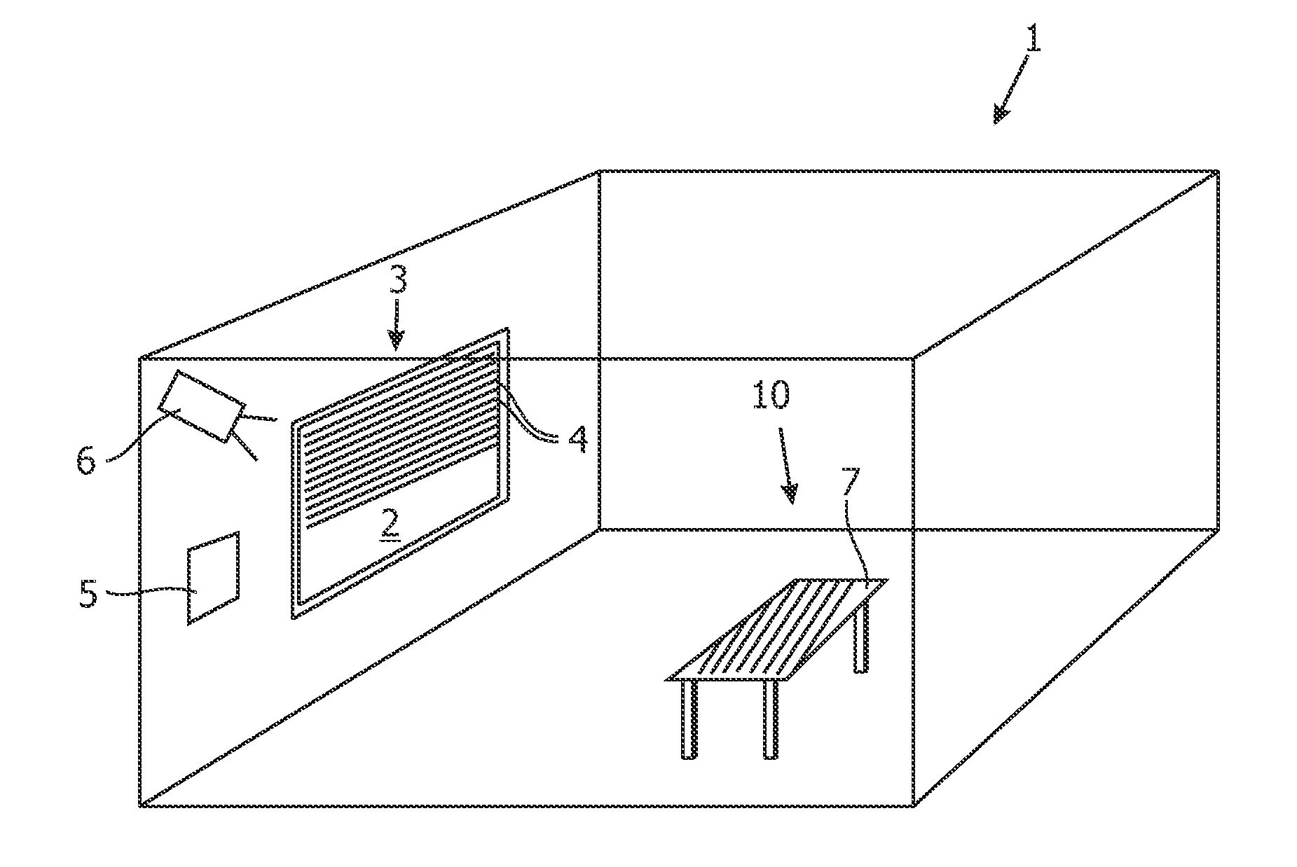
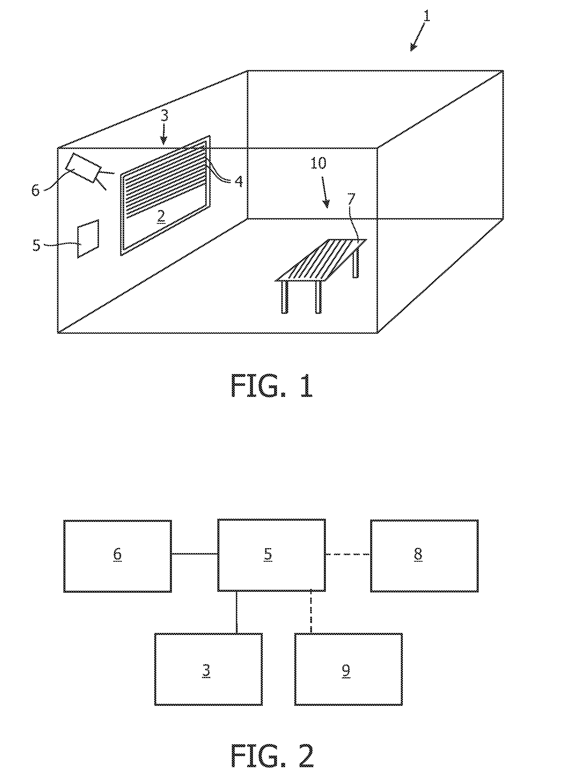
[0071]FIG. 1 shows a three-dimensional view of a system for controlling a shading device, installed in a room 1, e.g. a room of an office building. The room 1 comprises a window 2 to the outside of the office building.

[0072]The window 2 comprises a common venetian slat blind 3, having a plurality of separate rectangular slats 4, arranged horizontally. The angle of the slats 4, i.e. the tilt angle, is controllable using an electric motor and a corresponding suspension system (not shown). Furthermore, the height to which the slats are lowered is controllable.

[0073]The slat blind 3 is connected to a control unit 5 using a wireless connection for controlling the tilt angle of the slats 4.

[0074]A CCD camera 6 is arranged to observe the room 1 and especially a desk 7, shaded by the slat blind 3 from sunlight, falling through the window 2. The camera 6 is connected to the control unit 5 using a wireless connection.

[0075]A schematic block diagram of the system according to the present embod...

second embodiment

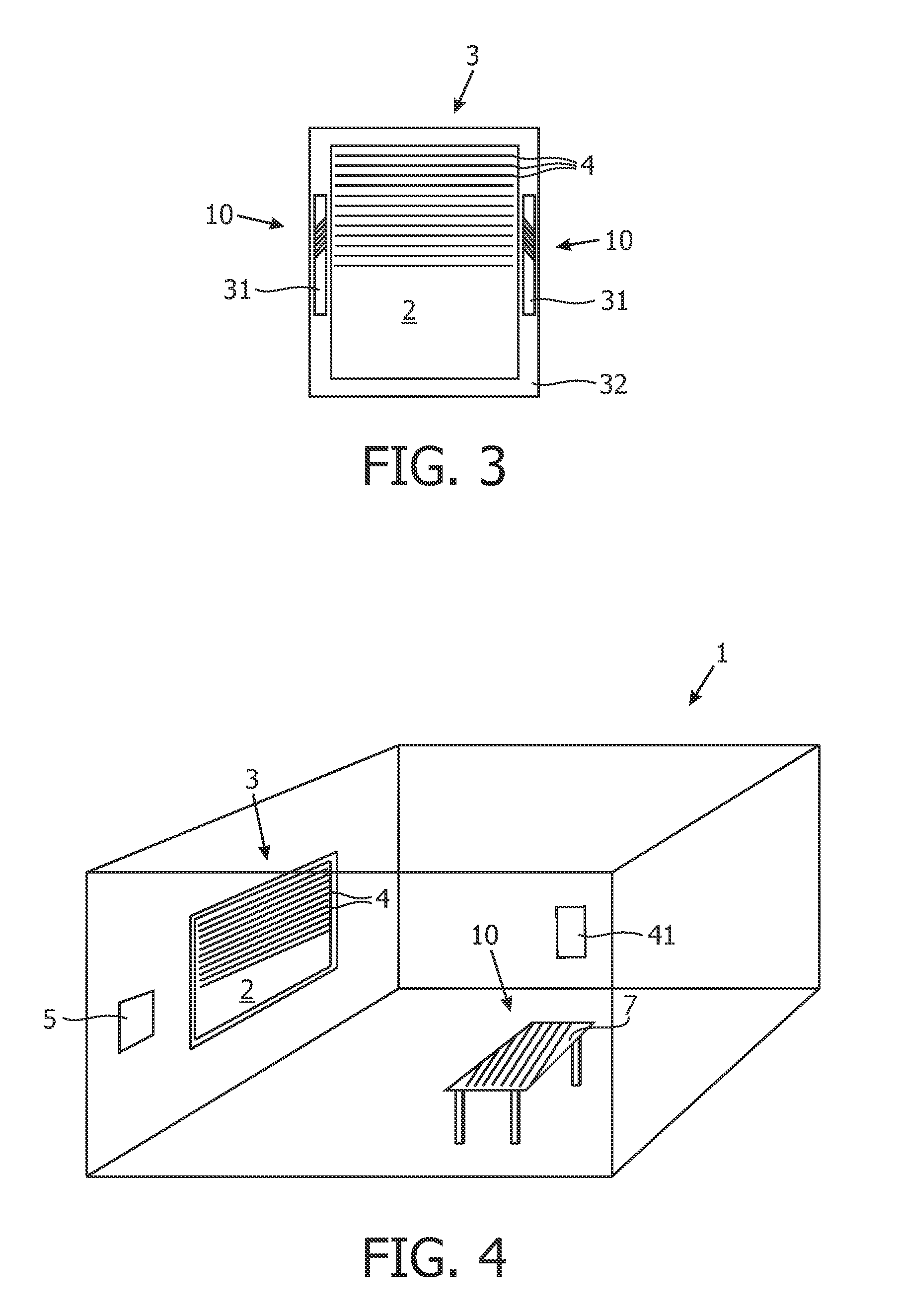
[0083]Additionally or alternatively to the arrangement of the camera 6, observing the room 1, sensor modules 31 may be provided on the window frame 32 of the window 2, as shown in the inventive system in FIG. 3.

[0084]The embodiment of FIG. 3 corresponds to the embodiment of FIGS. 1 and 2, with the exception that instead of a camera 6, two sensor modules 31 are arranged on the window frame 32 of the window 2 to detect the stripe pattern 10, allowing a very compact setup of the system.

[0085]The sensor modules 31 comprise e.g. linear sensor arrays of the type MRX90255BC, available from Melexis Corp. The details of the operation of the embodiment of FIG. 3 correspond to the embodiment of FIGS. 1 and 2.

third embodiment

[0086]the inventive system for controlling a shading device is shown in FIG. 4 in a three-dimensional view of the room 1. The present embodiment corresponds substantially to the embodiment of FIG. 1, but instead of a camera 6, a photodiode 41 is arranged in the room 1, connected to the control unit 5. The operation of the system, shown in FIG. 4 is hereinafter explained with the reference to the flow diagram of FIG. 5.

[0087]According to the present embodiment, a detection of glare resulting from direct light, transmitted through the shading device, is based on the detection of a change of the gradient of the luminance in the room 1 when varying the tilt angle of the slats 4.

[0088]In present embodiment, the control unit 5 is configured for conducting a calibration procedure, which is initiated in step 51 by the control unit 5 in response to a control command of the central control system 8 or of the manual controller 9. Alternatively, the procedure may be conducted on a periodic basi...


PUM


Abstract

The invention describes a system for controlling a shading device with a plurality of controllable shading elements. To provide a system for controlling a shading device, which reduces direct sunlight transmission and enhances thermal comfort and lighting conditions, the system comprises at least one detector unit for providing an image signal of a shading area and a control unit (5) being configured to receive said image signal, determine from said signal, whether a characteristic pattern is present in said shading area and in case said characteristic pattern is determined, control said shading elements to reduce said characteristic pattern.

Description

FIELD OF THE INVENTION[0001]The invention relates to a system and a method for controlling a shading device with a plurality of controllable shading elements.BACKGROUND OF THE INVENTION[0002]Shading devices, such as blinds, are used in a variety of commercial and household applications to keep excessive light and heat out of building structures, such as for example office buildings. Usually, shading devices are mounted either interior or exterior of windows or between the window panes and are controllable so that the amount of sunlight entering the building can be adjusted manually or using a suitable controlling system.[0003]Automatic controlling systems are known in the art, which control shading devices according to one or more measured environmental parameters, such as daylight conditions, wind or according to global building control settings or user preferences. Document WO 2008 / 149285 A1 discloses a controllable window blind having multiple slats, in which a tilt angle of said...

Claims


Application Information

Patent Timeline
IPC IPC(8): E05F15/20G05B15/02
CPCE06B9/322Y02B80/00Y02A30/24E06B9/24G05D25/00H04L12/12
Inventor ACKERMANN, BERND
Owner KONINKLIJKE PHILIPS ELECTRONICS NV
Learn More