
Passive remote detection of gas flow and cable arrival

a technology of gas flow and remote detection, applied in the direction of liquid/fluent solid measurement, instruments, optical elements, etc., can solve the problems of difficult task of recognizing or identifying the presence of signals from the far end, and the likelihood of being relatively faint, so as to avoid or reduce disadvantages, simple operation, and low manufacturing cost

Active Publication Date: 2012-02-02
BRITISH TELECOMM PLC
View PDF4 Cites 16 Cited by
  • Summary
  • Abstract
  • Description
  • Claims
  • Application Information

AI Technical Summary

Benefits of technology

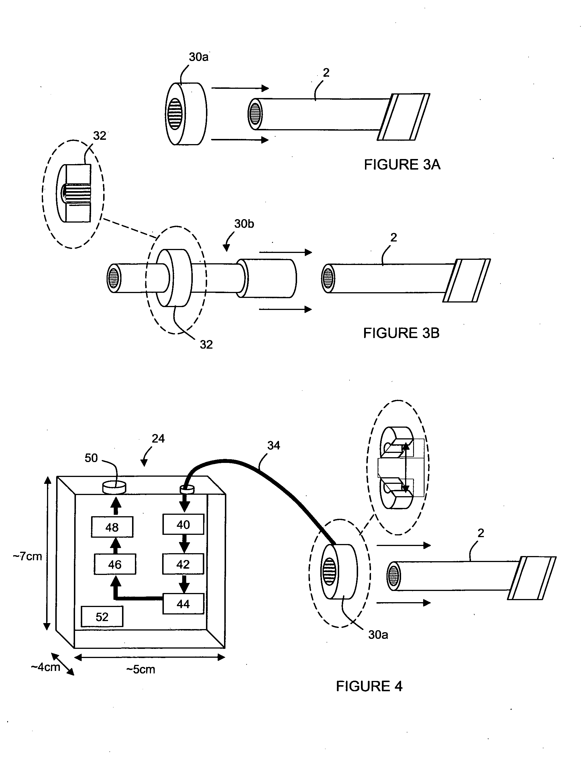
[0016]In general, embodiments of the present invention provide methods and devices for aspects relating to the installation of cables such as optical fiber units into conduit tubes using e.g. the blown fiber method, so that in particular, a single operator can operate substantially on his own at the head end, to determine if compressed gas and / or the fiber cable or unit fed into a conduit has reached its intended destination, and to then signal the arrival of gas and / or the fiber cable back to the head end in a way which avoids or reduces the disadvantages suffered above. Embodiments can be used where the operator has to choose between one of a number of conduits, or where there is a single conduit but where it is desirable to unambiguously confirm that the installation gas and / or the fiber unit will reach or reaches the intended destination. In view of the possible volumes that can be deployed in FTTx initiatives, embodiments also address the need for cost-efficiency in being relatively cheap to manufacture and simple to operate.

Problems solved by technology

As the signal can travel a significant distance from the remote far end of the tube to the near end where the detection apparatus is located, it is likely to be relatively faint.
Noise levels at the head end where the gaseous medium and the fiber unit are being installed into the tube are high, which makes the task of recognizing or identifying the presence of the signal from the far end even more difficult.

Method used


Image

  • Passive remote detection of gas flow and cable arrival
  • Passive remote detection of gas flow and cable arrival
  • Passive remote detection of gas flow and cable arrival

Examples


Embodiment Construction

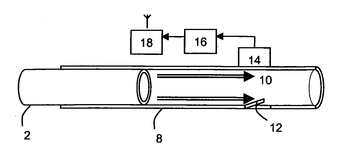
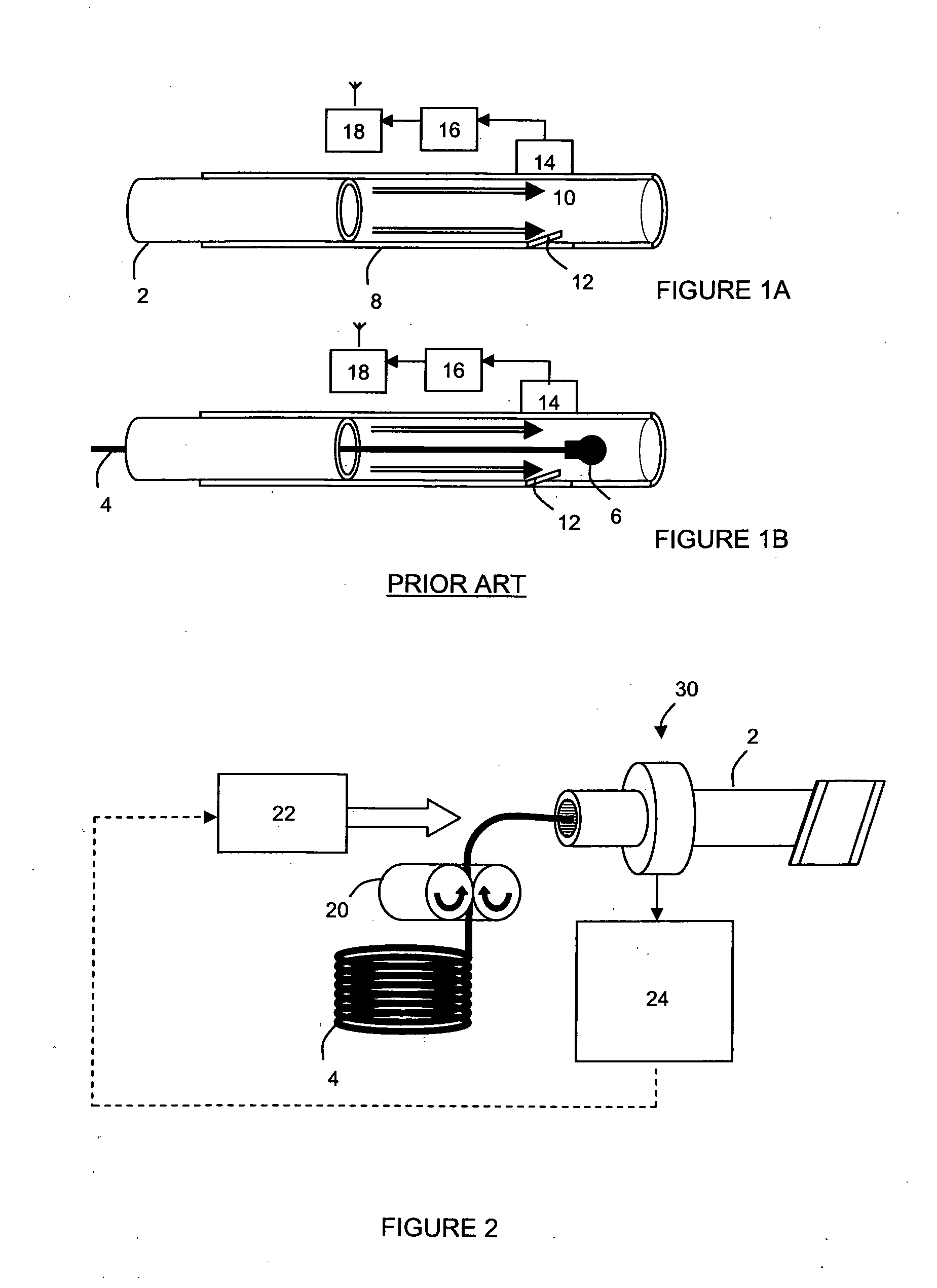
[0039]FIGS. 1A and 1B depict a sensor component (1) of the type which is described in PCT application GB2008 / 004284, the disclosure of which is hereby incorporated by reference herein in its entirety. This is fitted onto an end of an optical fiber tube (2), which extends from a near or local, end to a far, or remote, end, often as part of a network of conduits and tubes. Optical fiber is installed using the blown fiber method described above, from the near end towards the far end. In use, the operator first travels to the far end of the tube to fit the sensor unit onto the end of the tube which is to be populated by the optical fiber, before travelling back to the head end to operate the apparatus (typically comprising a blowing head and a compressor) to install the fiber into and through the tube.

[0040]As shown in FIG. 1, the sensor comprises a substantially cylindrical (which need not be of circular section) or tubular housing (8) which is open at both ends. The housing of the uni...


PUM


Abstract

A system for use in installation of blown fiber for detecting a signal indicative of presence of at least one of a gas flow or an optical fiber at a remote location, comprising a gas vibration detector configured to acoustically couple with an installation duct through which the signal can travel after its generation at the remote location, and a processor arranged to receive an input from the vibration detector and to process the input to identify the signal present within the input; and a sensor for generating the signal upon sensing the presence of at least one of the gas flow or the optical fiber at the remote location. The signal can be provided by a whistle mounted on the remote end of the installation duct. The vibration sensor is typically a microphone.

Description

RELATED APPLICATIONS[0001]The present application is a National Phase entry of PCT Application No. PCT / GB2010 / 000487, filed Mar. 18, 2010, which claims priority from European Patent Application No. 09250757.3, filed Mar. 19, 2009, the disclosures of which are hereby incorporated by reference herein in their entirety.TECHNICAL FIELD[0002]The present invention relates to the installation of cables, such as optical fiber units, wires, electrical cables or the like. More specifically, but not exclusively, the present invention relates to the blowing of fiber unit cables through pre-laid tubes.BACKGROUND ART[0003]Optical fibers are widely used within telecommunication systems for high-speed information transfer, particularly in the core or backbone network. Central to next generation telecommunications network and the roll out of broadband in e.g. the UK, is an all-optical fiber network throughout the core network which reaches out to customers (corporate users, enterprises, service prov...

Claims


Application Information

Patent Timeline
Patent Type & Authority Applications(United States)
IPC IPC(8): G01F1/66G06F19/00
CPCG02B6/4464G02B6/447G02B6/4466G02B6/4463G02B6/52G02B6/50G02B6/475G02B6/562
Inventor HEATLEY, DAVID JOHN TAYLORNEILD, IAN
Owner BRITISH TELECOMM PLC
Learn More