Rapid movement system for virtual devices in a computing system, management device, and method and program therefor

a computing system and virtual device technology, applied in the field of high-speed migration (rapid movement) of virtual devices, can solve the problems of not only overhead caused, but also overhead caused, and achieve the effect of reducing the service suspension period accompanying the migration

Inactive Publication Date: 2012-02-02
NEC CORP
View PDF11 Cites 41 Cited by
  • Summary
  • Abstract
  • Description
  • Claims
  • Application Information

AI Technical Summary

Benefits of technology

[0030]According to the present invention, a data copying operation is not performed. Instead, a high-speed storage device that is set separately from main memories is shared between physical devices, and an operation to transfer the right of possession to a specific area between the physical devices is perfor

Problems solved by technology

However, the period of time required for the transfer depends on the amount of data to be transferred, the overhead caused by the network bandwidth and the protocol processing, and the speed of memory reading and writing, for example.
In a specific example, a data transfer via a network protocol normally involves copying of

Method used


Image

  • Rapid movement system for virtual devices in a computing system, management device, and method and program therefor
  • Rapid movement system for virtual devices in a computing system, management device, and method and program therefor
  • Rapid movement system for virtual devices in a computing system, management device, and method and program therefor

Examples


example 1

[0129]Next, an operation of an embodiment for carrying out the present invention is described through a specific example.

[0130]FIG. 5 shows Example 1. As illustrated in FIG. 5, a first physical device 2000 and a second physical device 2100 include CPUs 2001 and 2101, NICs (Network Interface Cards) 2006 and 2106, SOUTHBRIDGEs 2005 and 2105, NORTHBRIDGEs 2003 and 2103, main memories 2002 and 2102, and Bridges 2004 and 2104, respectively. Hypervisors 2010 and 2110 such as Xen and VMWare operate in the first physical device 2000 and the second physical device 2100, to form a VM (Virtual Machine) 2022 that is being operated.

[0131]It should be noted that the VM 2022 is currently being operated in the physical device 2000, and, after a migration, will be operated in the physical device 2100. To make this aspect clear in the drawing, the VM 2022 in the physical device 2000 is shown by a dashed line, and the VM 2022 in the physical device 2100 after a migration is shown by a solid line.

[0132...

example 2

[0141]Example 2 of the present invention concerns an application to construction of a backup server.

[0142]In a specific example, a physical device 3000 is set as a master server, and a physical device 3100 is set as a slave (backup) server, as shown in FIG. 6. A NAND Flash is shared through a network switch as in the above described embodiment, and is mapped in the logical memory spaces of the physical devices 3000 and 3100. The physical device 3000 and the physical device 3100 share the NAND Flash, and part of the available area of the physical device 3000 is also made available to the physical device 3100. However, the physical device 3100 can perform only reading from the overlapping area. A VM 3020 is operated in the physical device 3000, and the memory area 3201 for the VM 3020 is reserved in the main memory. Meanwhile, the dirty memory is constantly copied into an area 3202 mapped in the NAND Flash in the background, and this area 3202 is the area that can be also accessed fro...


PUM


Abstract

In a virtualized computer system having at least two computers connected via a network, the service suspension period while a virtual device is dynamically migrated from a first computer to a second computer is shortened.
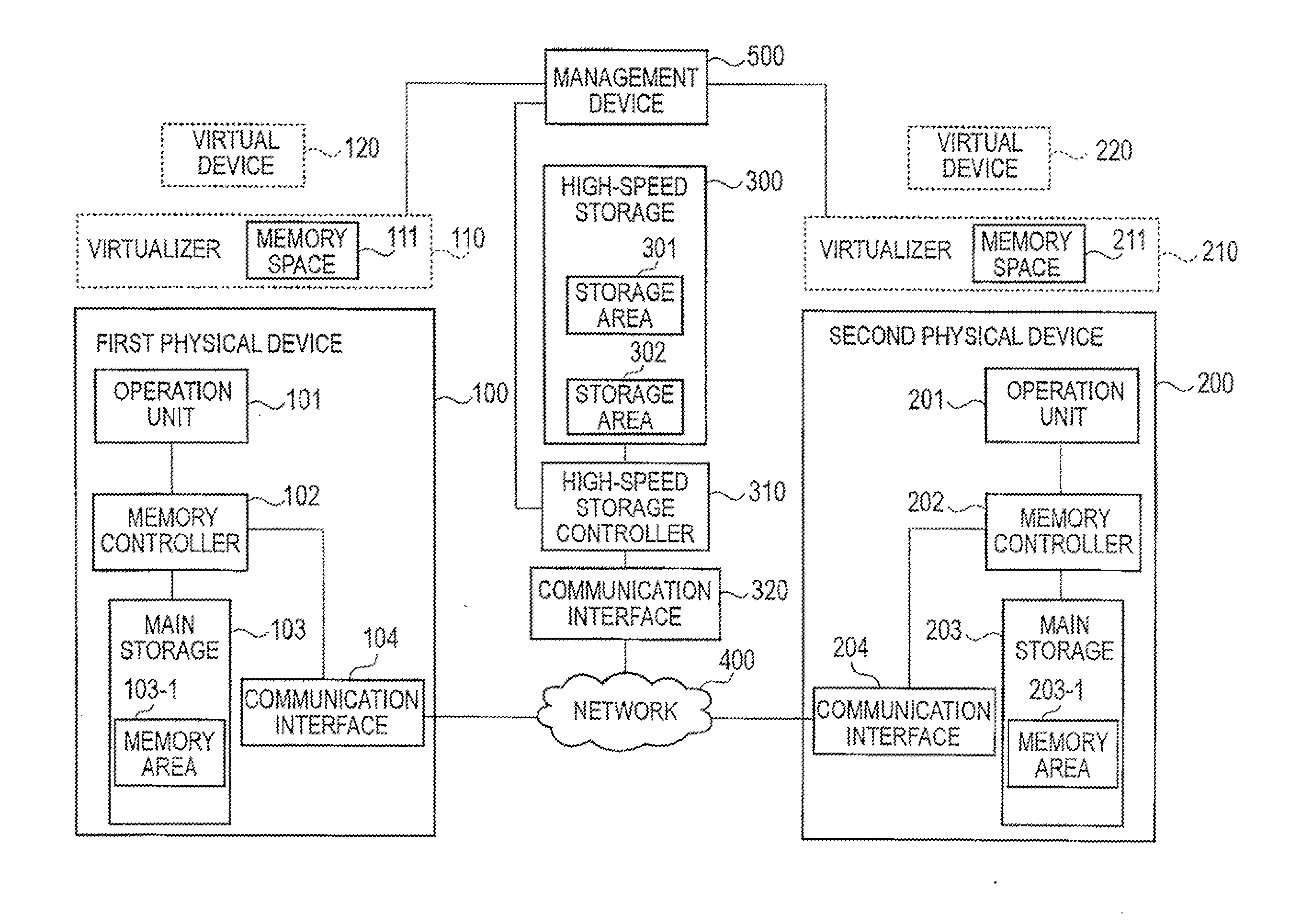
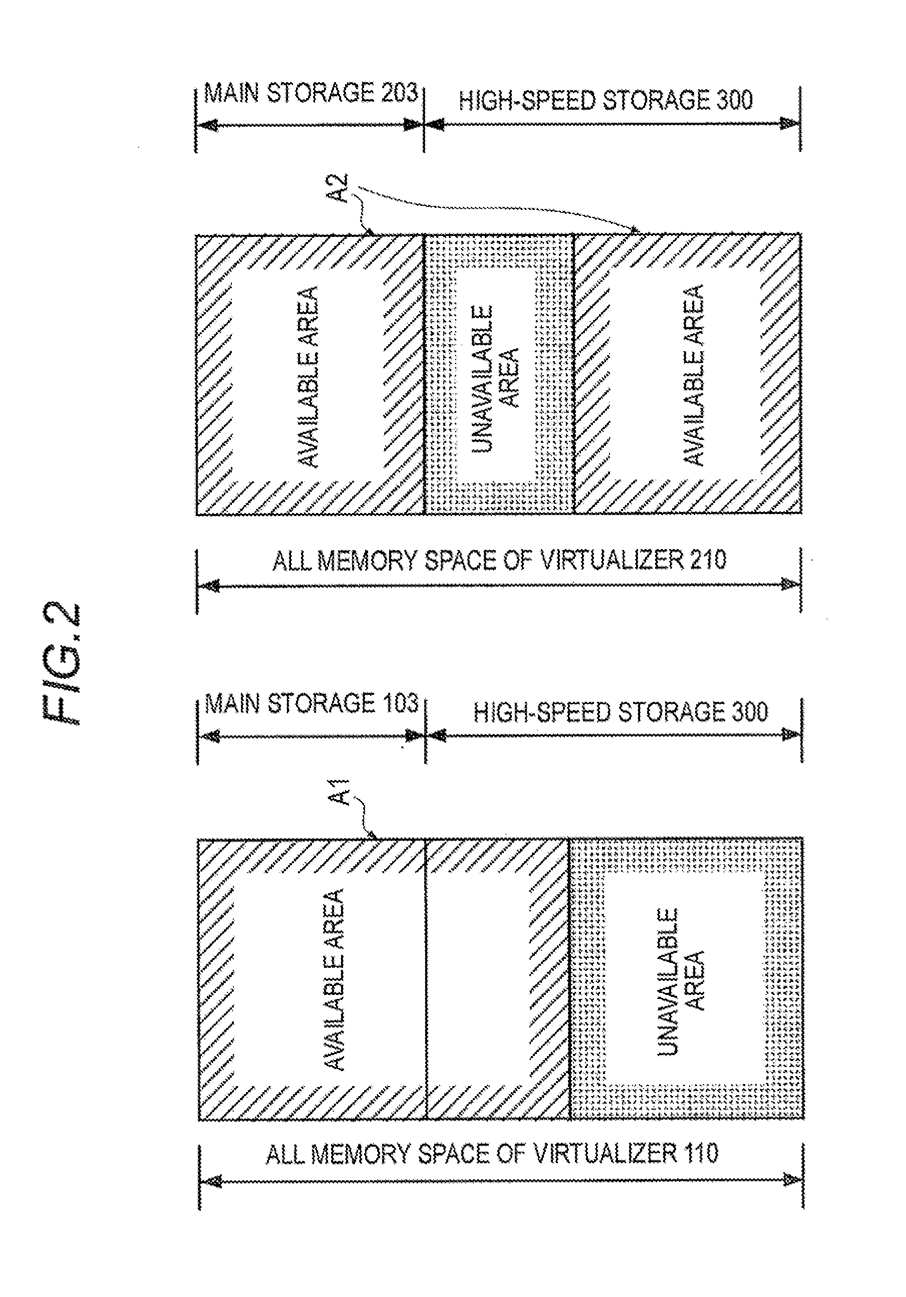
When the virtual device is migrated from the first physical device to the second physical device, memory data existing in an area mapped in the main memory of the first physical device is mapped in a high-speed storage device that is made available to the first physical device. The memory data is copied into an area that is registered in the second physical device but is made unavailable to the second physical device. During a temporary halt of the virtual device, a possession right transferring process is performed by changing possession right information about availability and unavailability of the high-speed storage device so that the area is made unavailable to the first physical device and is made available to the second physical device, thereby dynamically changing settings so that the virtual device can be operated with the use of the arithmetic processing unit of the second physical device.

Description

TECHNICAL FIELD[0001]The present invention relates to higher-speed migrations (rapid movement) of virtual devices in a computer system (computing system) formed with virtual devices in physical machines connected to one another via a network.BACKGROUND ART [0002]In a system having virtual devices formed in physical devices, a technique is normally used for migrating a virtual device between different physical devices in accordance with the usage states of the physical devices (see Patent Literature 1, for example).[0003]Non-Patent Literature 1 discloses an example of a technique concerning a higher-speed migration of a virtual device in a virtualized computer system formed with virtual devices as above. Referring to FIG. 7, this technique is described below.[0004]As shown in FIG. 7, this virtualized computer system includes a first physical device 1000 and a second physical device 1100.[0005]The first physical device 1000 includes a memory 1001 and a network interface card (NIC) 100...

Claims


Application Information

Patent Timeline
IPC IPC(8): G06F15/167
CPCG06F3/0617G06F3/0647G06F9/5077G06F3/0683G06F3/0662
Inventor KAMI, NOBUHARU
Owner NEC CORP
Why Eureka
Try Eureka