Device for conveying objects in packaging machines

a technology for conveying objects and packaging machines, applied in mechanical conveyors, conveyors, packaging, etc., can solve the problems of large number of individual parts and considerable control engineering, and achieve the effects of small mechanical effort, precise adjustment, and considerable speed

Inactive Publication Date: 2012-02-09
UHLMANN PAC SYST
View PDF8 Cites 10 Cited by
  • Summary
  • Abstract
  • Description
  • Claims
  • Application Information

AI Technical Summary

Benefits of technology

[0008]It is an object of the present invention to provide a device for conveying objects in packaging machines, in which the changeover to a new format can be accomplished with modest mechanical effort, with considerable speed, and with precise adjustment.

Problems solved by technology

Every automatic change or format requires in principle a large number of individual parts and a considerable amount of control engineering.

Method used


Image

  • Device for conveying objects in packaging machines
  • Device for conveying objects in packaging machines
  • Device for conveying objects in packaging machines

Examples


Embodiment Construction

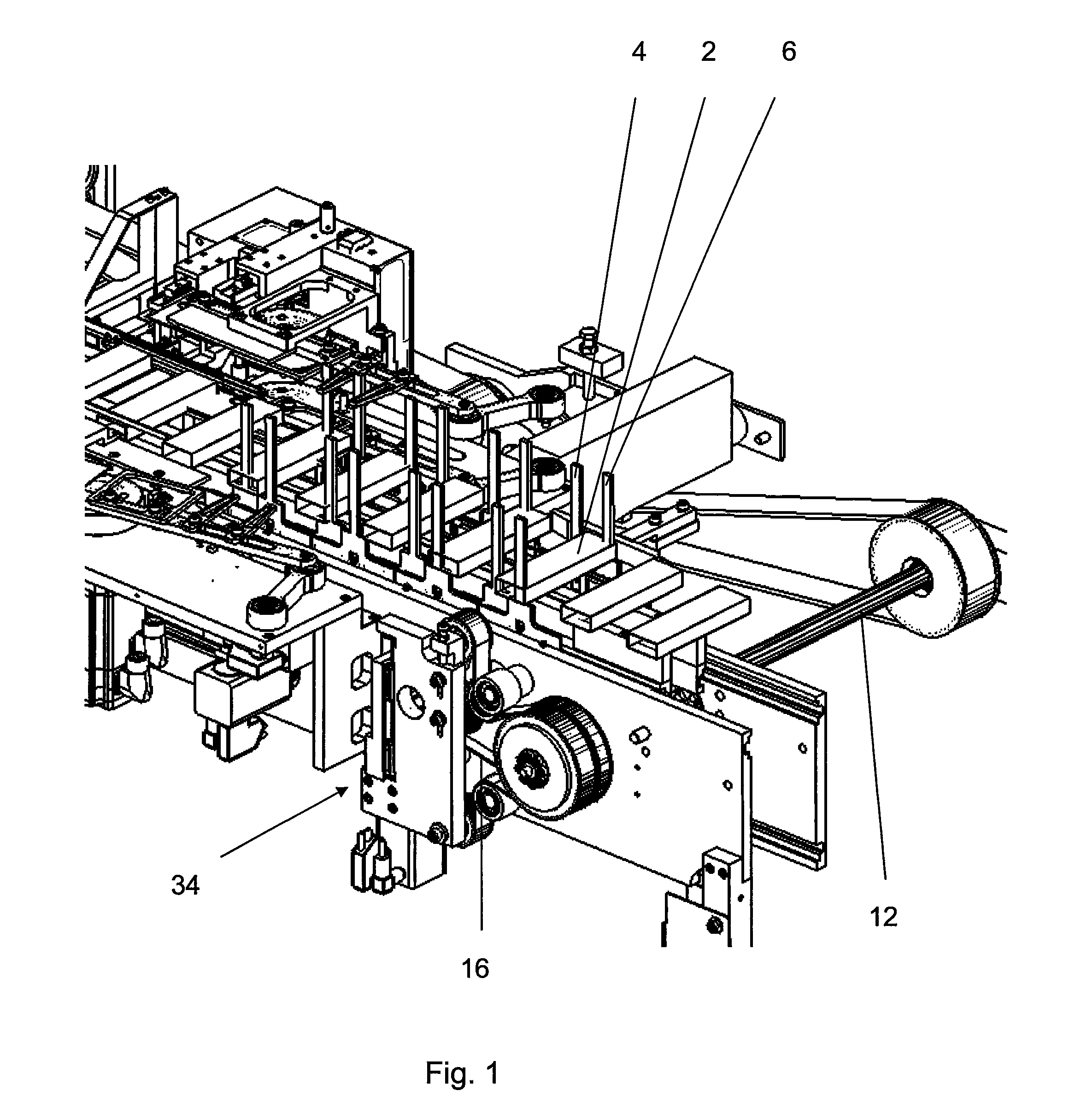
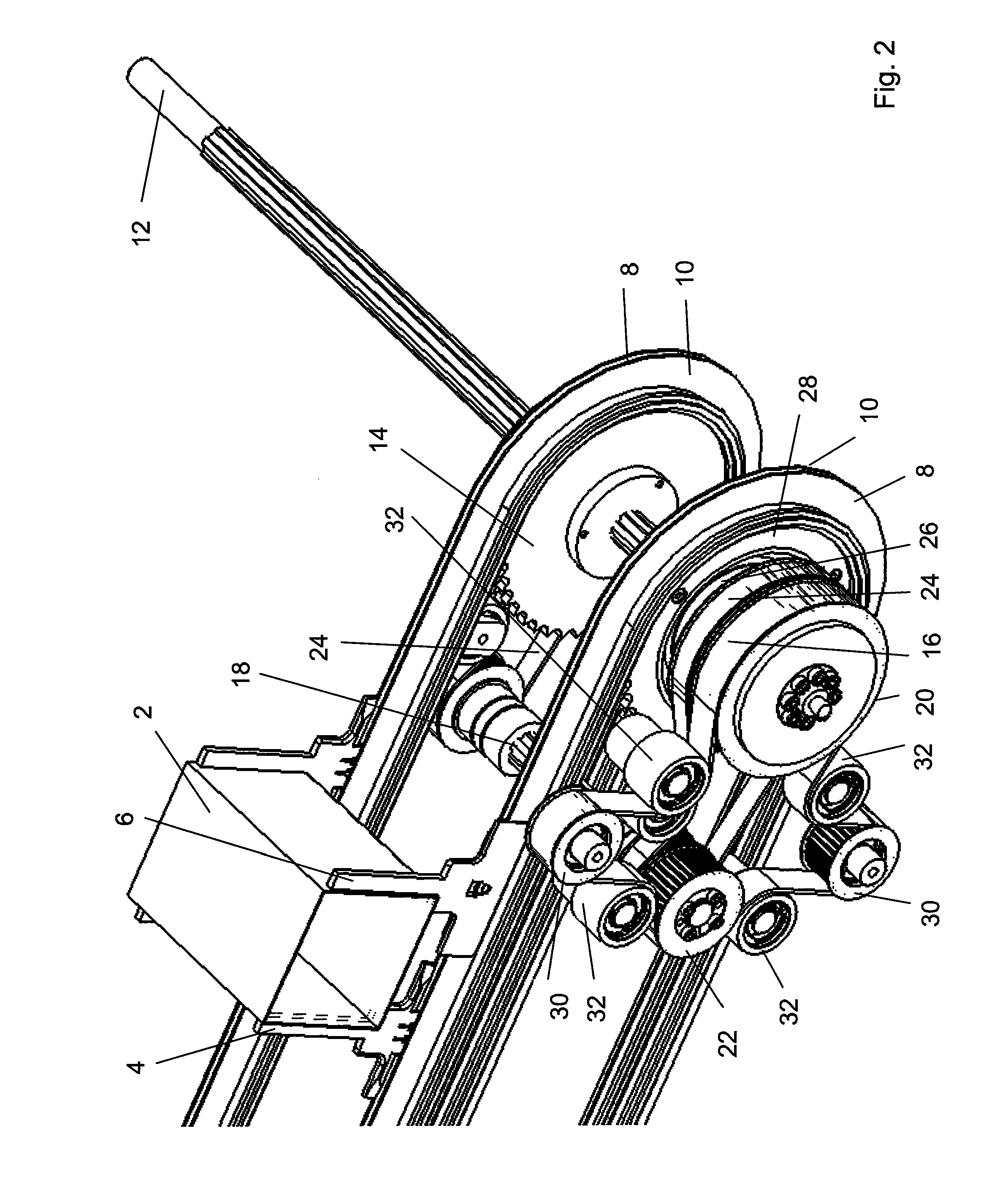
[0038]The invention is described in detail below with reference to the exemplary embodiment illustrated in FIGS. 1-8.

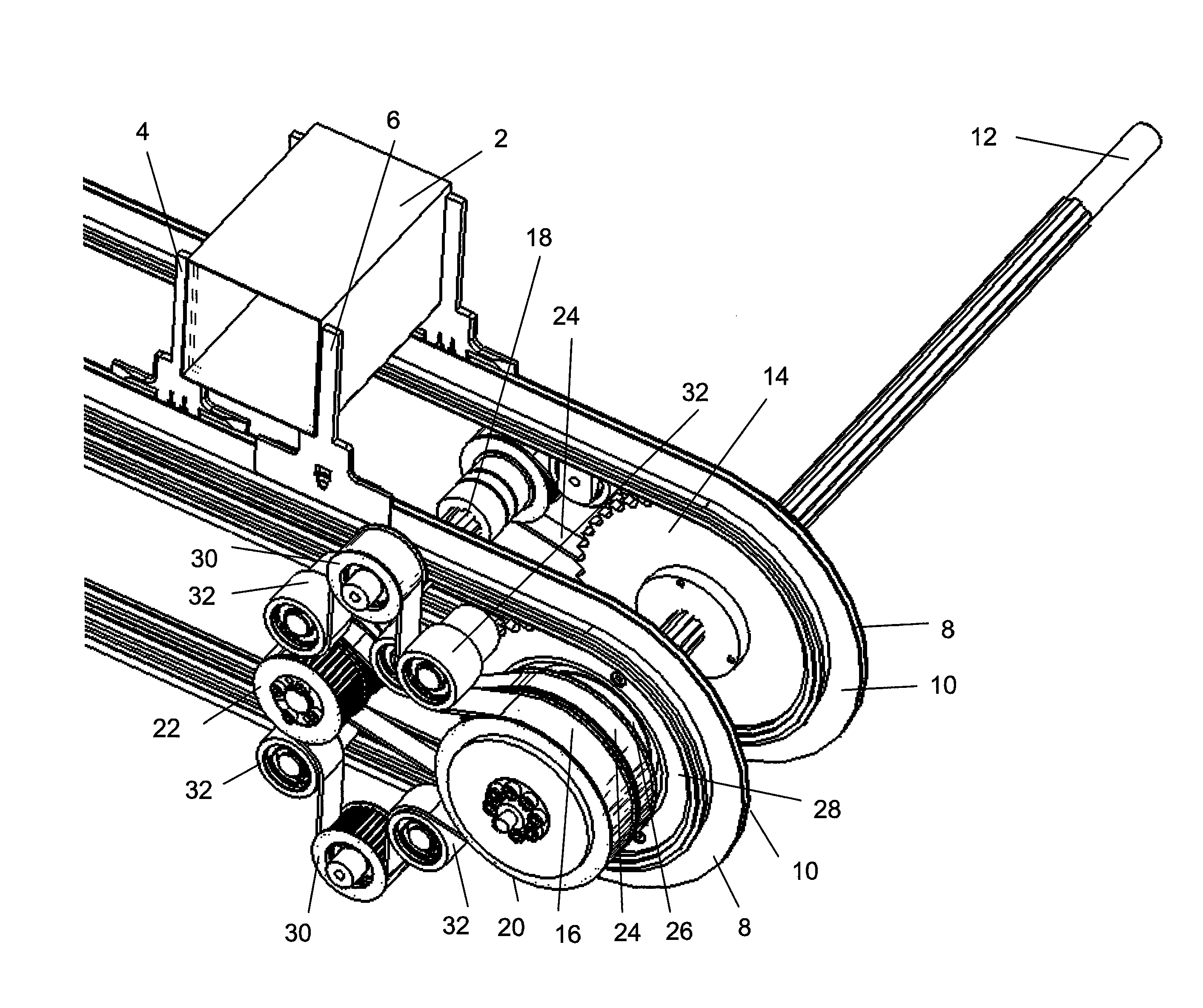
[0039]So that objects 2, especially folding boxes, can be transported during the packaging process, receiver cells adapted to the size of the objects 2 must be formed. Because the width of the receiver cells may have to be changed depending on the format of the objects 2 to be transported, it should be possible to adjust the size of the receiver cell slightly.

[0040]According to the present exemplary embodiment, each receiver cell is formed by first driver elements 4 and second driver elements 6 (see especially FIGS. 1 and 2). In the exemplary embodiment shown here, the first driver elements 4 are designed as pushing driver elements, whereas the second driver elements 6 are designed as counterholding elements. The opposite configuration is also conceivable. The driver elements 4, 6 can be designed as fingers as shown here, but they could also take the form of a continu...


PUM


Abstract

The device for conveying objects in packaging machines has a first endless transport unit, which moves first driver elements; a second endless transport unit, which moves second driver elements; a motor-driven drive shaft, which drives the first endless transport unit; an auxiliary shaft, which drives the second endless transport unit; and a belt-type or chain-type connecting element for transmitting drive power from the drive shaft to the auxiliary shaft. The connecting element is guided between the drive shaft and the auxiliary shaft over a plurality of stationary auxiliary rollers and over at least two adjusting rollers, which can be shifted simultaneously in a direction perpendicular to their axes of rotation. The connecting element is guided in such a way that a shift of the adjusting rollers brings about a movement of the connecting element on the auxiliary shaft and thus a change in the angular position of the auxiliary shaft.

Description

RELATED APPLICATIONS[0001]The present patent document claims the benefit of priority to European Patent Application No. EP 10172001.9, filed Aug. 5, 2010, and entitled “DEVICE FOR CONVEYING OBJECTS IN PACKAGING MACHINES,” the entire contents of each of which are incorporated herein by reference.FIELD AND BACKGROUND[0002]The invention relates to a device for conveying objects in packaging machines.[0003]These types of devices are used in particular in the pharmaceutical industry to transport folding boxes, into which stacks of blister packs are to be inserted. Such devices for conveying objects in packaging machines usually consist of two endless transport units, usually in the form of roller chains, which move the objects forward. The first transport unit, like the second unit, is equipped with driver elements in the form of upward-projecting fingers, for example, which serve to support the objects. Driver elements which function as pushing elements are assigned to the first transpo...

Claims


Application Information

Patent Timeline
Patent Type & Authority Applications(United States)
IPC IPC(8): B65G17/14
CPCB65B43/52B65G17/26B65B59/005B65B35/405B65B59/001B65B59/003
Inventor FELK, GUENTERFOCHLER, FRITZSTAHL, JOACHIM
Owner UHLMANN PAC SYST
Why Eureka
Try Eureka