Method of producing a multi-microchannel, flow-through element and device using same

Active Publication Date: 2012-02-09
NEW MEXICO TECH RES FOUND
View PDF8 Cites 43 Cited by
  • Summary
  • Abstract
  • Description
  • Claims
  • Application Information

AI Technical Summary

Benefits of technology

[0019]The multi-microchannel elements produced pursuant to the method of the present application, and the applications for such elements, have a number of benefits over conventional flow-through microfluidic technology. For example, the Nernst diffusion layer is reduced significantly, while at the same time clogging is prevented due to multi-microchannel element application with variations in geom

Problems solved by technology

Furthermore, the microchannels can merge into a single,

Method used


Image

  • Method of producing a multi-microchannel, flow-through element and device using same
  • Method of producing a multi-microchannel, flow-through element and device using same
  • Method of producing a multi-microchannel, flow-through element and device using same

Examples


Example

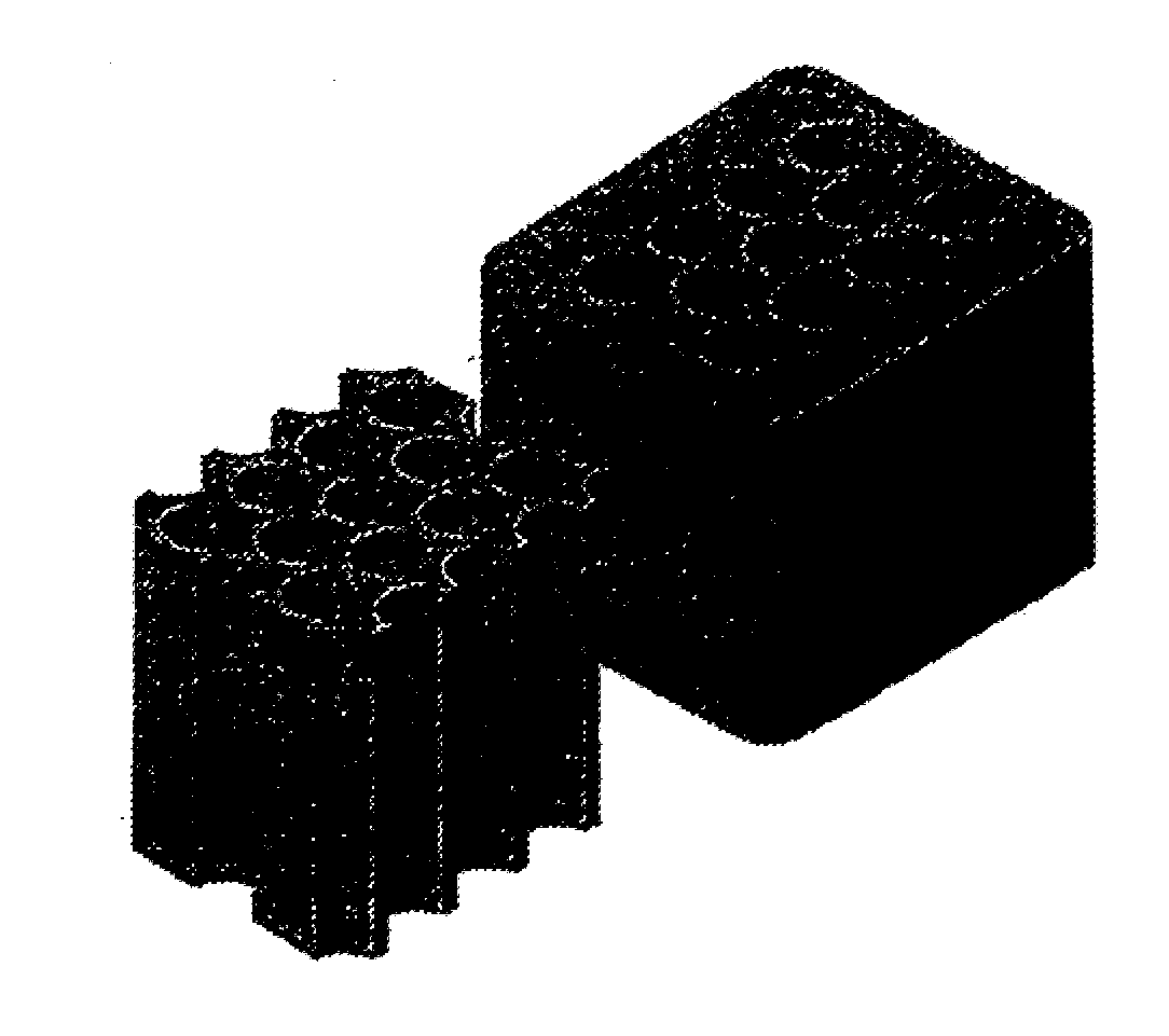
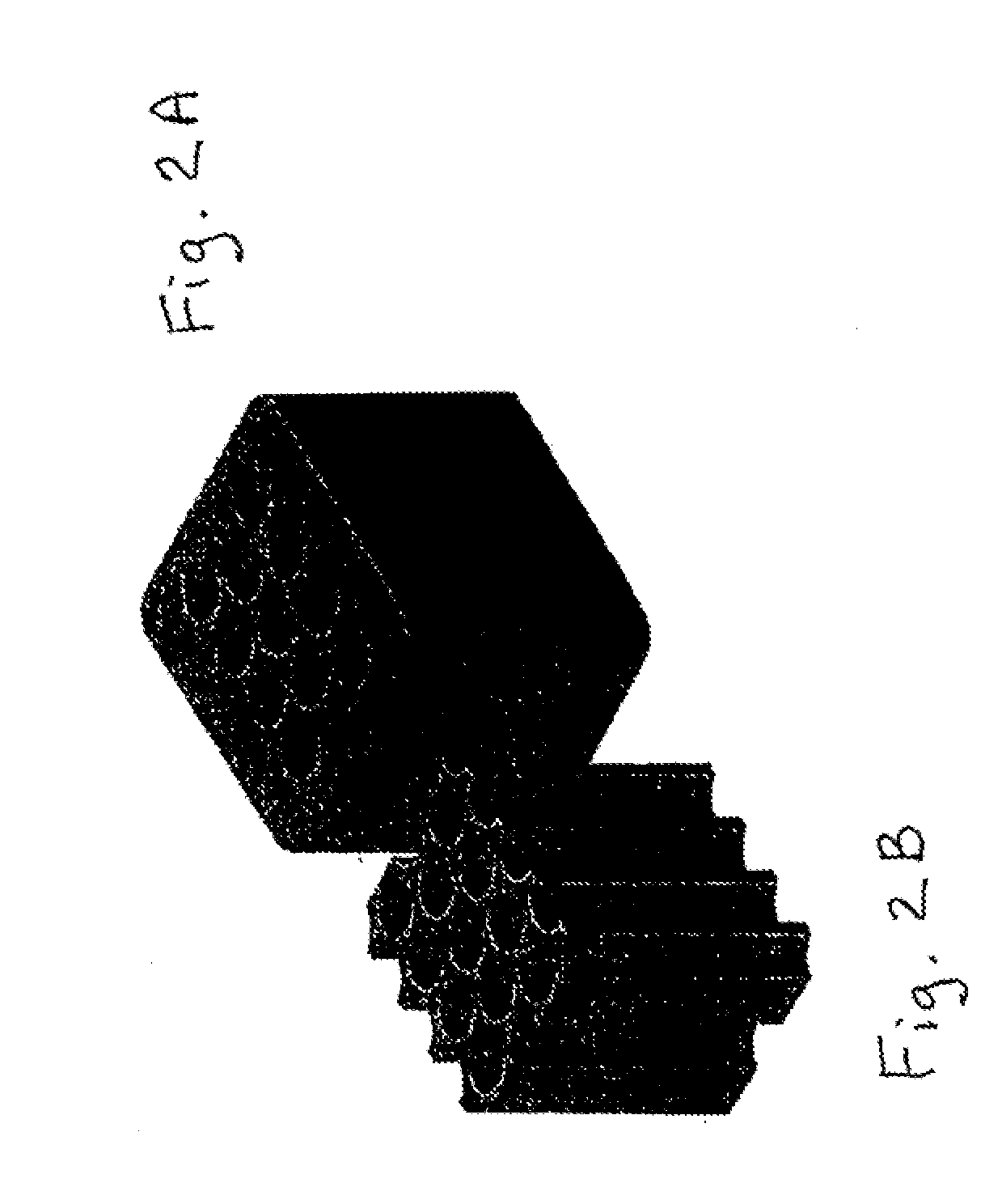
[0038]Referring now to the drawings in detail, the method of producing the multi-microchannel, flow-through element of the present application will first be described.

[0039]Pursuant to a presently preferred method, the production of such an element is based on the simultaneous decomposition of hydrogen-saturated fluid into solid and gaseous phases at a temperature lower than gas eutectic equilibrium. This produces multi-microchannels, with their specific geometry being determined by hydrogen concentration, direction and rate of solidification, and gas phase pressure at the solidification, as will be described in greater detail subsequently.

[0040]One exemplary method of producing a multi-microchannel, flow-through element utilizes an autoclave in which a base material, for example a single body of material, is melted in an atmosphere of a gas containing hydrogen, with the resulting melt being exposed to gas under a partial pressure of between 2.0 and 5.0 atmospheres in order to disso...


PUM

PropertyMeasurementUnit
Fractionaaaaaaaaaa
Diameteraaaaaaaaaa
Pressureaaaaaaaaaa

Abstract

A method of producing a multi-microchannel, flow-through element, including the steps of providing a body of material, and producing multiple microchannels within the body, wherein the microchannels extend through the body to produce a multi-microchannel, flow-through element. Such an element can be used as a micromixer, a sensor element, a filter, a fuel element or a chromatographic element.

Description

CROSS REFERENCE TO RELATED APPLICATION [0001]The present application is a continuation-in-part of U.S. application Ser. No. 11 / 201,699, filed Aug. 11, 2005, which is incorporated herein by this reference thereto.BACKGROUND OF THE INVENTION[0002]The present invention relates to a process for the manufacture of multi-microchannel elements and the use thereof.[0003]Miniaturization is the recent trend in analytical chemistry and life sciences. Similar to advances with integrated circuits in the computer industry, the area of biological and chemical analysis is also undergoing a miniaturization effort. A key benefit of miniaturization is the prospect of integration of all of the steps of an analytical process into a single device. With micron-scale forming, technologies for fluid flows and biosensors are now converging and the way is open for full integration of microfluidics with micro- and even nano-scale biosensors. The range of components that have been miniaturized and used as build...

Claims


Application Information

Patent Timeline
IPC IPC(8): B29D99/00B22D27/00B29C44/02
CPCB22F2999/00C22B9/023C22C1/08C22C2001/085B22F3/1121B22F2201/013C22C38/002C22C38/02C22C38/04C22C38/52Y02P10/20C22C1/085G01N27/327B29C44/02
Inventor IVNISKI, DMITRISHAPOVALOV, VLADIMIR
Owner NEW MEXICO TECH RES FOUND
Why Eureka
Try Eureka