Light emitting diode

a technology of light-emitting diodes and leds, which is applied in the direction of discharge tubes, discharge tubes, main electrodes, etc., can solve the problem of uniform color temperature of white light generated by leds

Inactive Publication Date: 2012-02-09
FOXSEMICON INTEGRATED TECH INC
View PDF0 Cites 29 Cited by
  • Summary
  • Abstract
  • Description
  • Claims
  • Application Information

AI Technical Summary

Problems solved by technology

Usually, the white light generated by the LED is not uniform in color temperature.

Method used


Image

  • Light emitting diode
  • Light emitting diode
  • Light emitting diode

Examples


Embodiment Construction

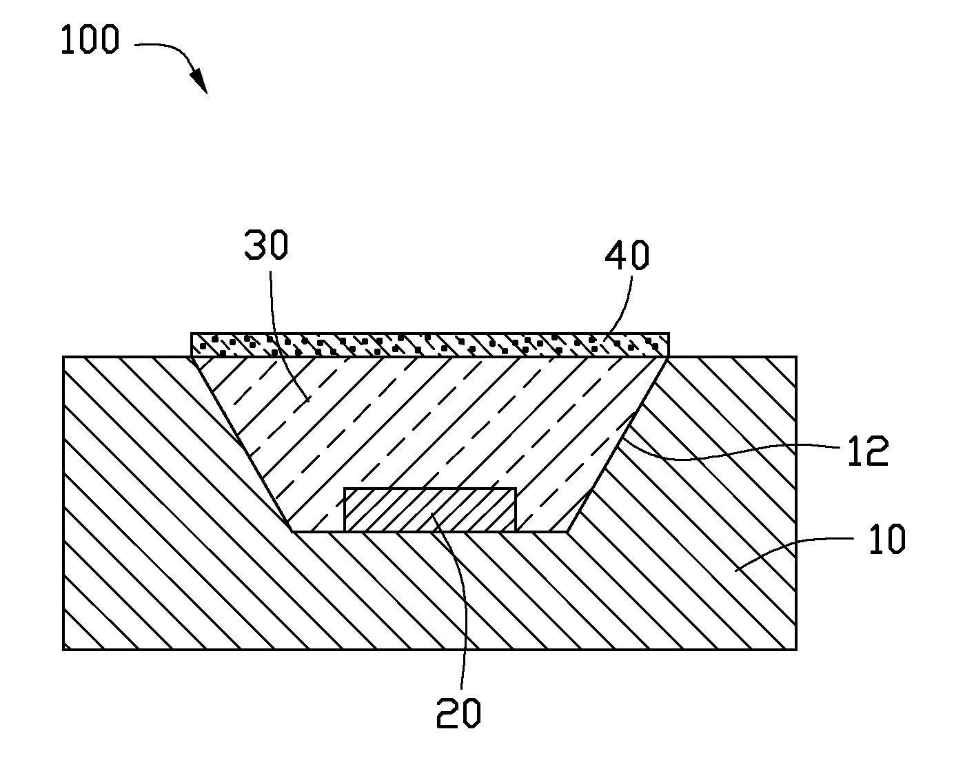
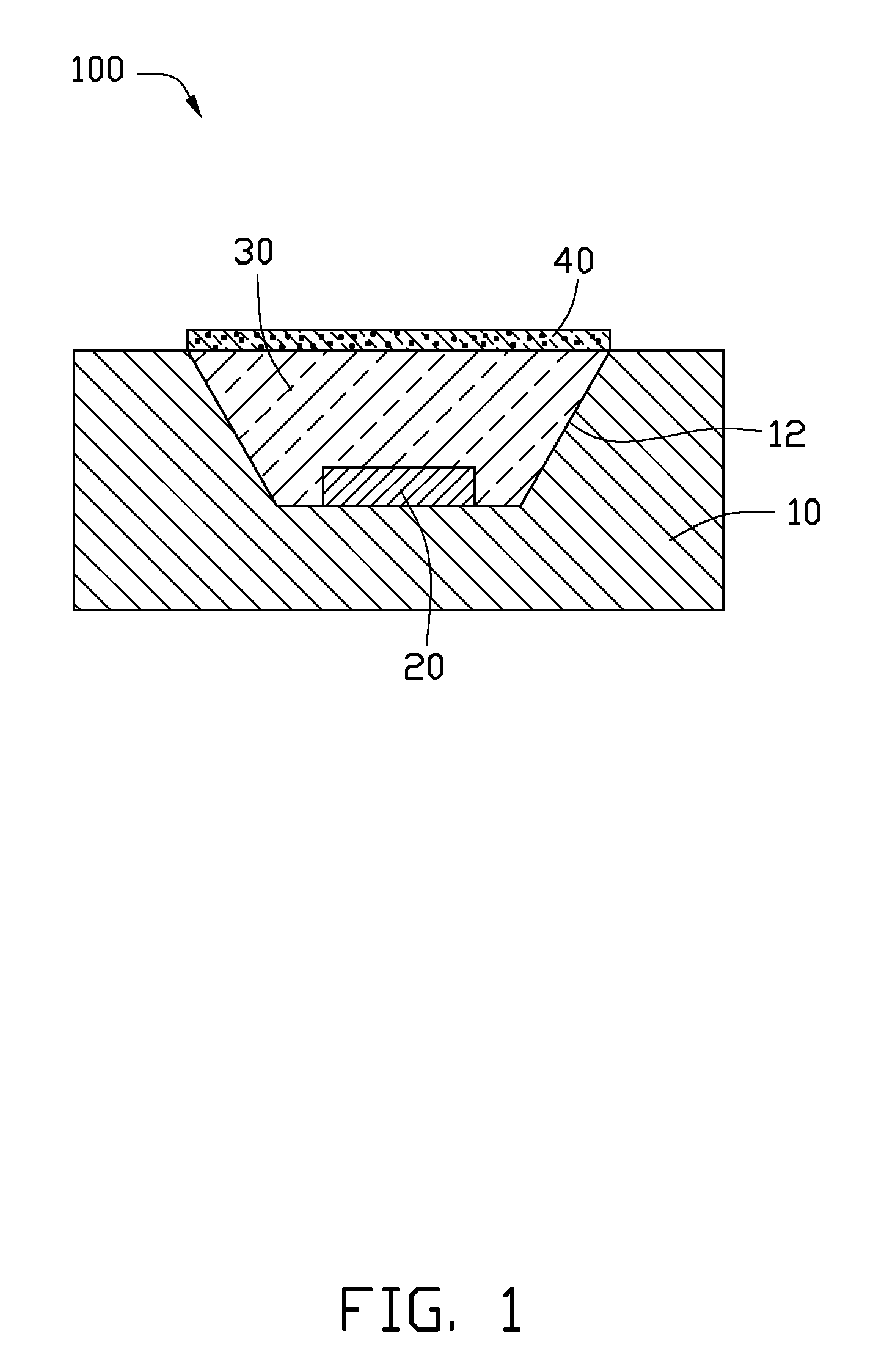
[0011]Referring to FIG. 1, an LED 100 in accordance with a first embodiment is shown. The LED 100 is capable of emitting visible light with a first color temperature, and includes a substrate 10, an LED chip 20 thermally attached to the substrate 10, an encapsulation 30 encapsulating the LED chip 20, and a phosphor layer 40 containing phosphor particles and disposed on an outer surface of the encapsulation 30.

[0012]The substrate 10 can be made of metallic material, such as copper, copper-alloy, aluminum or aluminum-alloy. The substrate 10 can also be made of a ceramic material with properties of electrically insulating and high thermal conductivity, such as Al2O3, AlN, SiC or BeO2. A groove 12 with a trapeziform cross section is defined in a top face of the substrate 10. The LED chip 20 is received in the groove 12 and attached to an inner face of the groove 12. The encapsulation 30 is filled in the groove 12, and the outer surface of the encapsulation 30 is coplanar with the top fa...


PUM


Abstract

An LED comprises a substrate, an LED chip mounted on the substrate, an encapsulation encapsulating the LED chip, and a phosphor layer containing phosphor particles disposed on an outer surface of the encapsulation. A luminous intensity I of light generated by the LED chip and a radiation angle θ are in Lambertian distribution and satisfy following formula: I=I0×cos θ, here the radiation angle θ is not lower than 0°, and is not higher than 90°, and I0 is a luminous intensity at a central axis of the LED chip, and the radiation angle θ is an angle between the light and the central axis. One of parameters of concentration, particle number of the phosphor particles in the phosphor layer and a thickness of the phosphor layer is also in Lambertian distribution relative to the radiation angle θ.

Description

BACKGROUND[0001]1. Technical Field[0002]The present disclosure relates to LEDs (light-emitting diodes), and more particularly to an LED coated with a phosphor layer.[0003]2. Description of Related Art[0004]An LED (Light-Emitting Diode) as a new type of light source can generate brighter light, and have many advantages, e.g., energy saving, environment friendly and longer life-span, compared to conventional light sources. The LED generally includes an LED chip emitting blue light and a phosphor layer containing phosphor particles deposited on the LED chip. A portion of the blue light emitted by the LED chip and red and green light emitted by the phosphor layer as a result of a partial absorption of the blue light can combine to produce white light.[0005]Usually, the white light generated by the LED is not uniform in color temperature. For example, this nonuniformity is a consequence of the variations in the thickness of the phosphor layer. The thickness of the phosphor layer causes n...

Claims


Application Information

Patent Timeline
Patent Type & Authority Applications(United States)
IPC IPC(8): H01L33/52F21V29/00
CPCH01L33/507H01L33/642H01L33/508
Inventor LAI, CHIH-MING
Owner FOXSEMICON INTEGRATED TECH INC
Why Eureka
Try Eureka