Stabilizing drive for contactless rotary blood pump impeller
What is Al technical title?
Al technical title is built by PatSnap Al team. It summarizes the technical point description of the patent document.
a technology of rotary blood pump and impeller, which is applied in the field of centrifugal rotary blood pump, can solve the problems of thrombosis and sometimes hemolysis, large size and prone to mechanical wear, premature wear, and thrombosis of the blood
Active Publication Date: 2012-02-09
HEARTWARE INC
View PDF0 Cites 81 Cited by
Summary
Abstract
Description
Claims
Application Information
AI Technical Summary
This helps you quickly interpret patents by identifying the three key elements:
Problems solved by technology
Method used
Benefits of technology
[0024]A centrifugal rotary blood pump for implantation within the pericardial space includes a housing defining a pumping chamber. The pumping chamber has an axial blood inlet and a tangential volute defining a blood outlet. One or more magnetic motor stators are provided outside of the pumping chamber. A rotatable impeller is within the pumping chamber and is adapted to pressurize blood entering the pumping chamber for exiting at the blood outlet. The impeller has one or more magnetic regions. The impeller is radially and axially suspended in rotation by magnetic forces created by passive and active sources of magnetic flux acting upon the impeller and one or more hydrodynamic thrust bearings provided on an upper surface of the impeller. The housing assembly may have an upper or front casing and a rear or lower casing which, when assembled, form a substantially cylindrical pumping chamber and a volute having a tangential blood outflow port. In one embodiment, when assembled, the housing defines a substantially cylindrical pumping chamber. A relatively short inflow cannula is integrated with the upper casing and is adapted for insertion into a ventricle of the heart. The outflow port is directed perpendicular to the axis of the inflow cannula. The blood inflow cannula may be straight, curved or otherwise bent to facilitate the fit of the blood pump into the thoracic cavity of the patient or to improve blood flow characteristics.
[0027]Alternatively, the impeller bodies may be formed as hollow titanium casings. Each such casing defines an interior cavity which may be fitted with a permanent magnet. Each inserted magnet is held within its associated cavity by a cap element or by a circular disk that covers the bottom of the impeller. In either case, the cap or disk is hermetically sealed to the casing, such as by laser welding. Solid walls between the hollow casings may contain a plurality of bores to modify the weight of the impeller and to provide consistent rotation. A passive magnetic bearing provides radial impeller support for rotation of the impeller around a center post within the housing without contact with the post during operation of the pump. In one embodiment, the magnetic bearing for the impeller is created by repulsive forces of magnetic vectors provided by corresponding permanent magnets. Magnetic vectors created by one or more such permanent magnets located within the impeller are adapted to repel magnetic vectors resulting from one or more permanent magnets located within the center post around which the impeller rotates without contact during pump operation. Such an arrangement provides radial stiffness for the rotating impeller and leaves an open space between the impeller and the center post which defines a portion of another of several fluid flow paths through the impeller.
[0028]In one embodiment, the axial alignment between the magnets within the impeller and the magnets within the center post is adjustable to provide repulsive magnetic preload forces acting on the impeller in an axial direction opposite to the axial forces imposed on the impeller as a result of hydrodynamic thrust. The magnetic preload enables the impeller to avoid contact between its bottom surface and an interior surface of the lower pump casing. This ensures yet another blood flow path around the impeller which enables fluid pressure within the pumping chamber to keep blood below the impeller in motion since blood is moved from beneath the impeller up through the annular space between the impeller and the center post around which it rotates. The magnetic preload may also be sufficient to restore the impeller to its original position should it undergo a significant shock event. Motor electromagnetic forces may also provide supplemental axial magnetic preload as well as supplemental radial impeller support. Magnetic preload enables the impeller to avoid contact between its bottom surfaces and the lower interior surface of the lower pump housing casing. During operation, the axial force produced by hydrodynamic thrust bearing surfaces on the upper projection surfaces of the impeller bodies moves the impeller away from the upper wall of the housing but permits a blood flow path between the lower projection surfaces of the impeller and the lower wall of the housing. Fluid pressure within the pumping chamber keeps blood in motion below the impeller. Blood may move from beneath the impeller up through the open center of the impeller as the impeller rotates.
[0030]The method of operation includes apical implantation of a short inflow cannula into the left ventricle of a heart, pressurizing the inflowing blood fluid within a pumping chamber by causing rotation therein of an impeller without mechanical contact with the impeller, positioning the rotating impeller to be suspended within the chamber so as to be completely submerged in the inflowing blood fluid, causing the inflowing blood fluid to traverse at least three flow paths within and around the impeller whereby pressure within the pumping chamber causes continuous flow of the blood from the inflow to an outflow from the pumping chamber, and directing the outflowing blood through a tube graft to the aorta.
Problems solved by technology
Such pumps are normally provided with check valves that only permit flow in one direction and are normally large and prone to mechanical wear.
This too became a source of thrombosis and sometimes hemolysis, as well as premature wear.
The use of seals for mechanical shafts in rotary blood pumps has been shown to be suboptimal as seals could cause thrombosis of the blood and could wear out prematurely.
While passive magnetic bearings may be effective at keeping the impeller suspended in one direction, for example in the radial direction, it has been shown that such passive magnetic bearings alone cannot keep an impeller suspended in both the axial and radial directions.
Method used
Image
Click on the blue label to locate the original text in one second.
Reading with bidirectional positioning of images and text.
Examples
Embodiment Construction
[0043]In describing the embodiments of the present invention illustrated in the drawings, specific terminology is employed for sake of clarity. However, the present disclosure is not intended to be limited to the specific terminology so selected, and it is to be understood that each specific element includes all technical equivalents which operate in a similar manner.
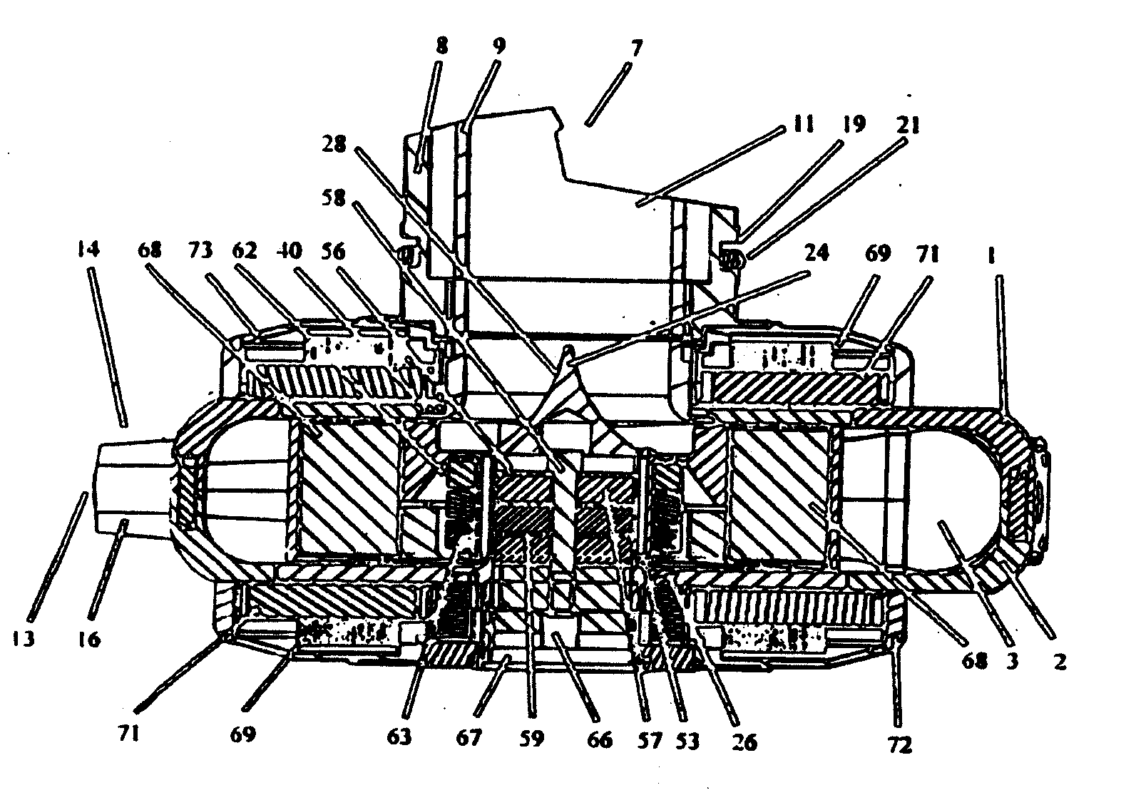
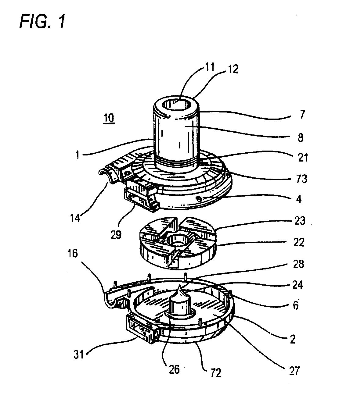
[0044]Referring now to FIG. 1 there is shown a rotary blood pump 10 having a pump housing that consists of a substantially circular front or upper pump casing 1 and a substantially circular rear or lower pump casing 2 of equal diameter that interlocks with the upper pump casing 1 to form a closed pumping chamber between them. The configuration of the upper and lower pump casings is such that the assembled pump housing defines a substantially cylindrical pumping chamber 3 therein (FIG. 5). In one embodiment the pumping chamber has a displaced volume of 45 cc. The upper pump casing 1 may have a plurality of peripheral pos...
PUM
Abstract
A rotary blood pump includes a casing defining a pumping chamber. The pumping chamber has a blood inlet and a tangential blood outlet. One or more motor stators are provided outside of the pumping chamber. A rotatable impeller is within the pumping chamber and is adapted to cause blood entering the pumping chamber to move to the blood outlet. The impeller has one or more magnetic regions. The impeller is radially constrained in rotation by magnetic coupling to one or more motor stators and is axially constrained in rotation by one or more hydrodynamic thrust bearing surfaces on the impeller.
Description
[0001]This application is a continuation-in-part of U.S. Ser. No. 11 / 654,226, filed Jan. 16, 2007, now U.S. Pat. No. 7,976,271, issued Jul. 12, 2011, which claims the benefit of U.S. Provisional Applications Nos. 60 / 758,793, filed Jan. 13, 2006; 60 / 758,892, filed Jan. 13, 2006; 60 / 758,795, filed Jan. 13, 2006; and 60 / 758,794, filed Jan. 13, 2006, the entire contents of which are hereby incorporated by reference.FIELD OF TEE INVENTION[0002]The present invention relates to rotary pumps and, more specifically, to centrifugal rotary blood pumps and methods of therapeutic support utilizing such pumps, in which an impeller within the pump rotates on wearless hydrodynamic and magnetic bearings which permit blood to be moved from a pump inlet to a pump outlet by the impeller in contact only with the volume of blood within the pump.BACKGROUND OF THE INVENTION[0003]Clinical applications of ventricular assist devices to support patients with end-stage heart disease, as a bridge to cardiac tran...
Claims
Application Information
Patent Timeline
Application Date:The date an application was filed.
Publication Date:The date a patent or application was officially published.
First Publication Date:The earliest publication date of a patent with the same application number.
Issue Date:Publication date of the patent grant document.
PCT Entry Date:The Entry date of PCT National Phase.
Estimated Expiry Date:The statutory expiry date of a patent right according to the Patent Law, and it is the longest term of protection that the patent right can achieve without the termination of the patent right due to other reasons(Term extension factor has been taken into account ).
Invalid Date:Actual expiry date is based on effective date or publication date of legal transaction data of invalid patent.
Patent Type & Authority Applications(United States)