Minimally-invasive retroperitoneal lateral approach for spinal surgery

a retroperitoneal lateral and minimally invasive technology, applied in the field of minimally invasive retroperitoneal lateral approach for spinal surgery, can solve the problems of pain and sometimes debilitating nerve impingement syndrome, unfettered anterior spinal exposure for precise midline placement of prosthetic discs, and significant surgical disruption of the anterior annular element around the dis

Inactive Publication Date: 2012-02-09
PANTHEON SPINAL
View PDF17 Cites 78 Cited by
  • Summary
  • Abstract
  • Description
  • Claims
  • Application Information

AI Technical Summary

Benefits of technology

[0010]The inventor has found it is advantageous to provide a method, device and system that permit an angle between a disc implant and insertion instrument to be altered without removing the implant from the intervertebral space. This new surgical approach also removes the native disc contents from a generally lateral direction, which permits the peritoneal contents to fall out of the surgical field, while also taking advantage of the mechanics of anterior interbody surgery.
[0012]In one embodiment, an implant is positioned in the intervertebral disc space of a laterally positioned subject by accessing the anterior face of the spinal disc intervertebral space, between the L5 and S1 vertebrae, from an anterolateral retroperitoneal approach. An oblique operative corridor is then established to the anterior face of the spinal disc space by introducing a retractor instrument anterolaterally to the spinal disc space, for example anterior to the anterior superior iliac spine, and in some instances between the level of the anterior superior iliac spine and the anterior inferior iliac spine. The spinal disc contents are removed from the intervertebral space through the operative corridor, and an elongated implant is introduced through the operative corridor into the intervertebral space diagonally (at an angle). The elongated implant is then pivoted within the intervertebral space to eventually position the implant substantially medial-laterally within the intervertebral space and achieve midline symmetric distribution of the mechanical load on the implant. The ability to pivot the implant within the intervertebral space permits the elongated implant to be generally aligned with the insertion instrument and advanced into the body through a relatively narrow operative corridor, then turned to its final position within the intervertebral space.
[0015]In some disclosed embodiments, the implant is an elongated elastomeric member that has a top bearing face, a bottom bearing face, a front face, a rear face, an ipsilateral face and a contralateral face. The rear face of the implant may be substantially flat. The contralateral face of the implant may be rounded (particularly at its corners that adjoin the front and rear faces) to minimize trauma induced by advancing the implant diagonally into the intervertebral space at the oblique angle, and using the ipsilateral face to function as an impact hinge or pivot point as the implant is moved in one or more realignments from the oblique to medial-lateral orientation. The ipsilateral end of the implant may have a pivot axis and an interface element, such as multiple pairs of spaced docking holes arranged on a curved surface that extends partially circumferentially around the pivot axis. The selected pairs of spaced docking holes are positioned to mate with the docking element of the introducer instrument, such as a pair of docking pins that extend from a distal tip of the introducer instrument.
[0017]The retractor instrument may also take a variety of forms, but certain disclosed embodiments have an ipsilateral arm that is shorter than the contralateral arm. A retractor blade on the ipsilateral arm therefore extends a shorter distance from the handle than the retractor blade on the contralateral arm. This asymmetric arrangement permits the retractor instrument to be advanced diagonally through the body from an anterolateral entrance point through the abdominal wall to the anterior aspect of the vertebral body. Since the contralateral arm is longer than the ipsilateral arm, the retractor blades at the anterior vertebral body span the anterior face of the vertebral body, for example from the 10 o'clock to 2 o'clock positions. The retractor blades may be curved outwardly from a longitudinal axis of the retractor instrument to help minimize damage to the blood vessels as they are retracted. A thin shim with a tapered tip may be inserted into the intervertebral space and mounted to the ipsilateral blade to retain the instrument in its desired angular orientation and distract adjacent vertebral bodies (such as L5 and S1) apart from one another during the procedure. The shim curves inwardly into the disc space, toward the midline of the body, away from the ipsilateral retractor blade, and toward a longitudinal axis of the retractor instrument. The shim has a height sufficient to maintain the adjacent vertebral bodies spaced from one another while a trial spacer and subsequent disc implant are pivoted into place within the disc space.

Problems solved by technology

The intervertebral discs can be damaged or undergo degeneration, which often results in painful and sometimes debilitating nerve impingement syndromes.
Procedures such as total disc arthroplasty (disc replacement) have used a direct anterior approach orthogonal to the midline of the vertebral body, but such procedures require unfettered anterior spinal exposure for precise midline placement of the prosthetic disc.
The procedure also causes significant surgical disruption of the anterior annular element around the disc.
Injury to the left iliac vessel is an unfortunate complication of such procedures.
The direct lateral retroperitoneal approach to the L5-S1 space has not been possible because the anterior superior iliac spine obstructs a direct lateral approach to the L5-S1 intervertebral space.
Minimally invasive surgical approaches to the intervertebral spaces in the past have also been limited by the need to insert the prosthetic disc implant either into the front portion, posterior portion, or the side of the disc space to achieve stable placement of the prosthetic implant.

Method used


Image

  • Minimally-invasive retroperitoneal lateral approach for spinal surgery
  • Minimally-invasive retroperitoneal lateral approach for spinal surgery
  • Minimally-invasive retroperitoneal lateral approach for spinal surgery

Examples


Embodiment Construction

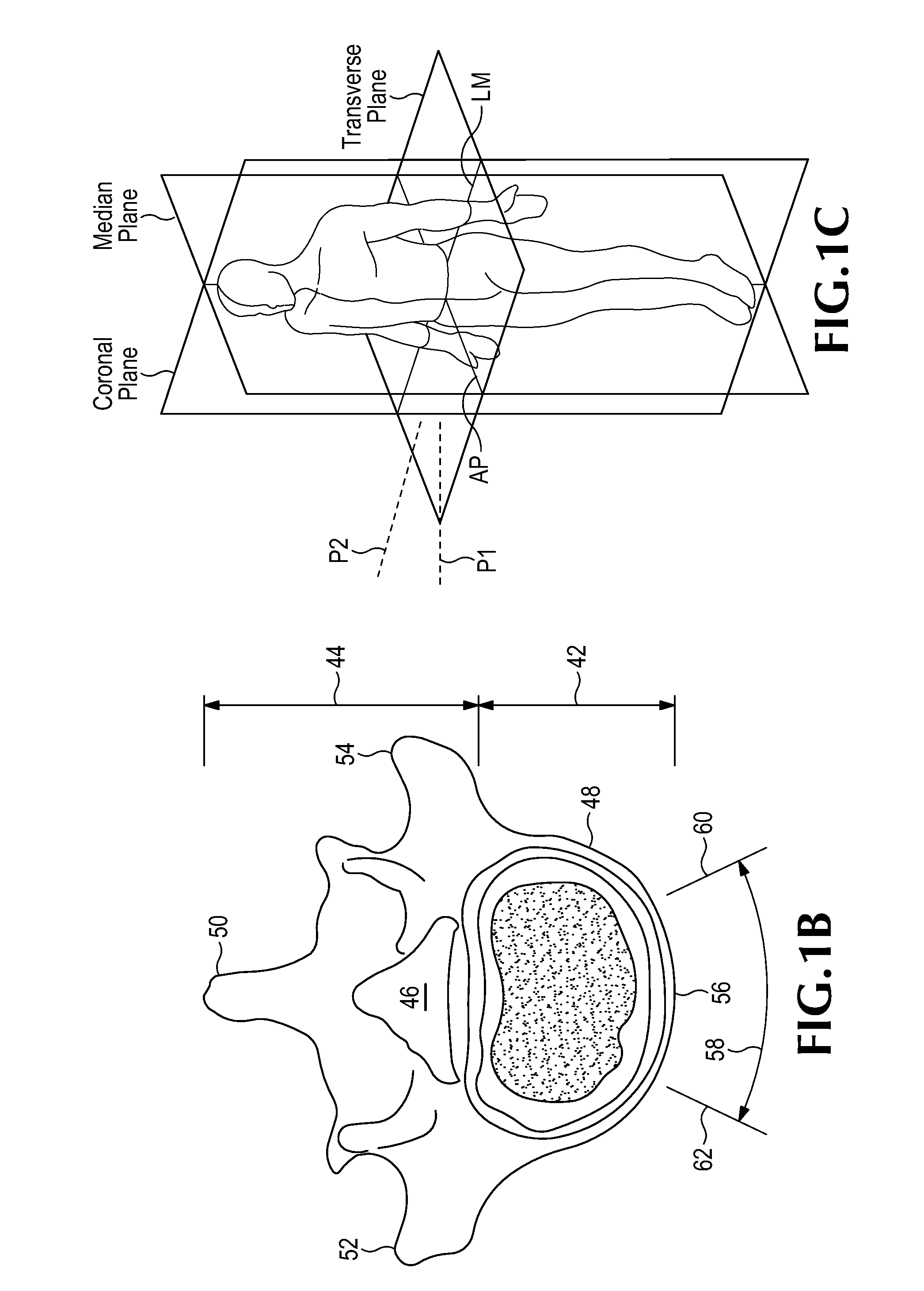
[0063]Embodiments of the invention are disclosed herein for accessing an intervertebral space, such as the L5-S1 space, and implanting a prosthetic disc implant within that space. The disclosed devices, methods and systems are suitable for use in a minimally invasive procedure for repairing degenerated or otherwise injured intervertebral discs.

General Overview of the Surgical Procedure

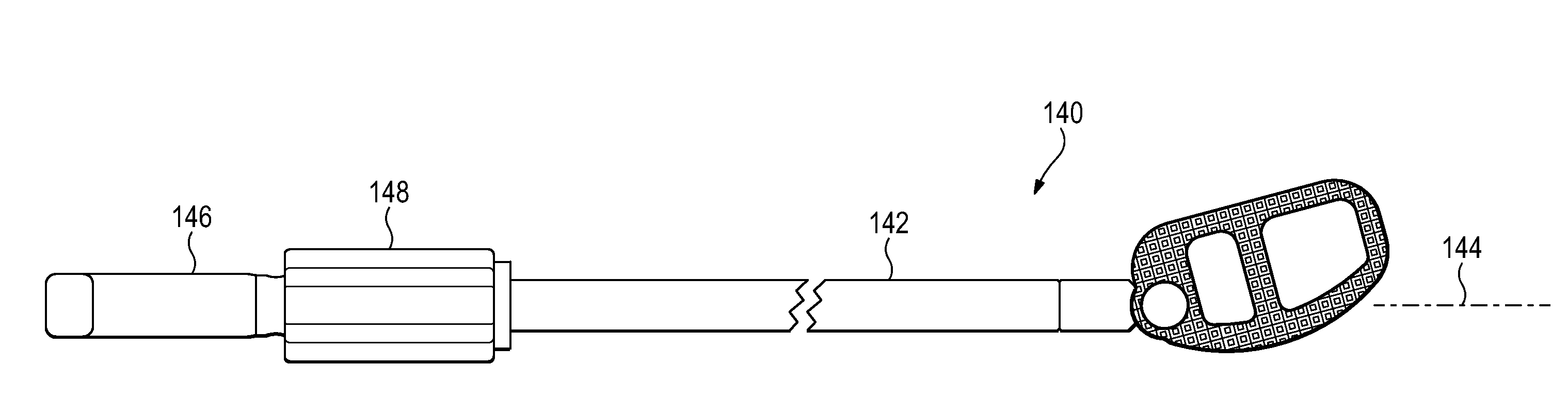
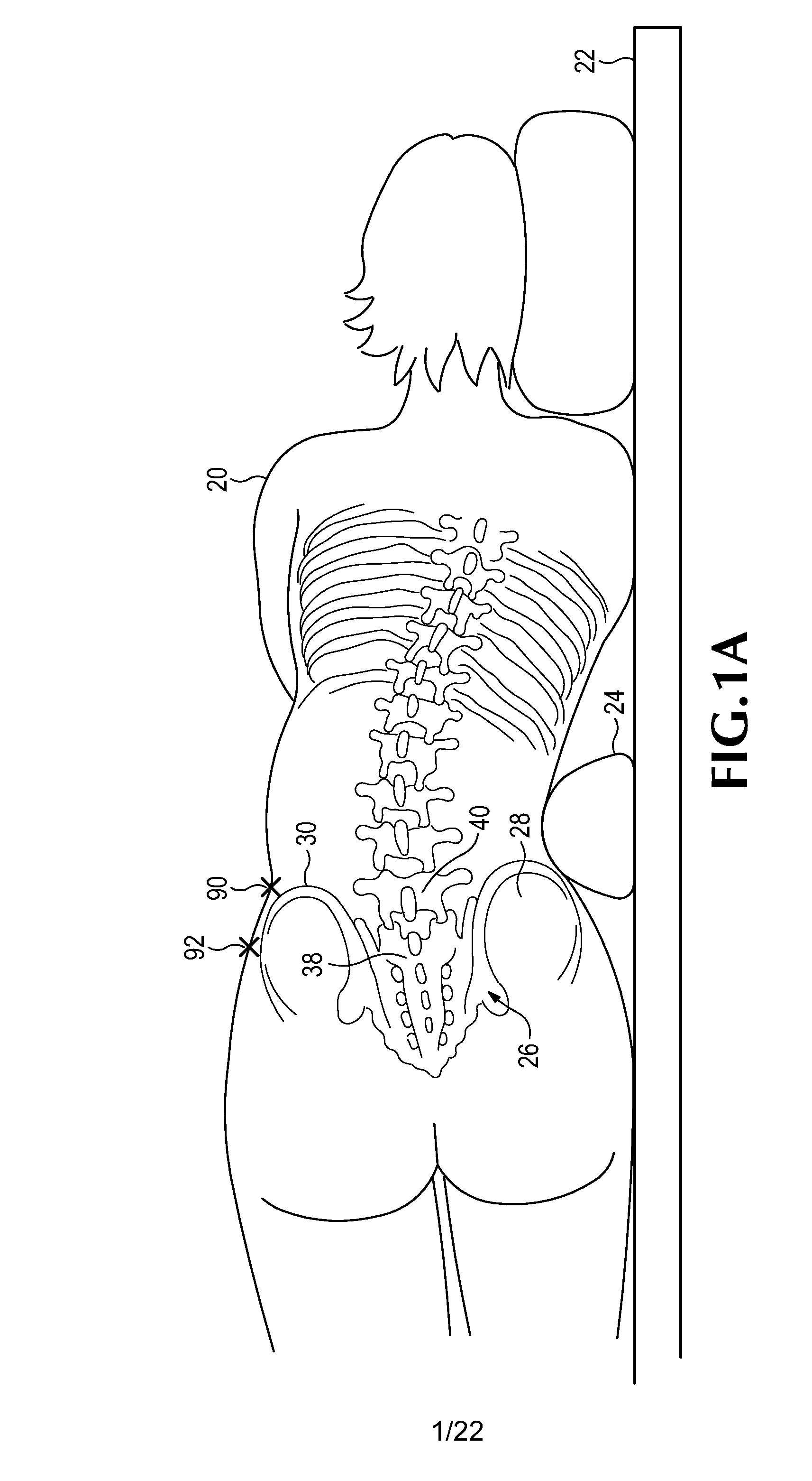
[0064]The method generally includes initially accessing the intervertebral space using a retroperitoneal lateral approach. Then, with a finger-directed dilator or other suitable instrument, the distal retroperitoneum is swept anteriorly to expose an eventual channel to a direct approach to L5-S1. In most people, the direct approach to L5-S1 is anterior to the anterior superior iliac spine, or between the anterior superior iliac spine and the anterior inferior iliac spine. An incision is then made to open this channel, and blunt dilators are directed in an oblique direction directly to the mid-anterior ...


PUM


Abstract

A method is disclosed for introducing a spinal disc implant into an intervertebral space of a subject. The subject is placed in a lateral position, and the anterior face of the spinal disc intervertebral space is accessed, between the L5 and S1 vertebrae, from an anterior and lateral retroperitoneal approach. An operative corridor to the anterior face of the spinal disc space is established by introducing a retractor instrument anterolaterally to the spinal disc space between the anterior superior iliac spine and the anterior inferior iliac spine. The damaged spinal disc contents are removed from the intervertebral space through the operative corridor, and the implant is advanced into the intervertebral space at an oblique angle and pivoted to position the implant substantially laterally within the intervertebral space. Elongated retractor and insertion instruments, as well as a modified disc implant, are also disclosed for carrying out the method.

Description

CROSS REFERENCE TO RELATED APPLICATIONS[0001]This application claims priority to and the benefit of U.S. Provisional Application No. 61 / 140,926, filed Dec. 26, 2008, and U.S. Provisional Application No. 61 / 178,315, filed May 14, 2009, both of which are hereby incorporated by reference in their entireties.FIELD[0002]Spinal surgery methods and devices are disclosed for repairing damaged or deteriorated vertebrae at the lower lumbar levels, such as in the L5-S1 intervertebral space.BACKGROUND[0003]The vertebral column is the central pillar of the body. It is a generally flexible column that bears tensile and compressive loads, permits bending motions, and provides an attachment site for ribs, muscles and other structures. The vertebral column includes irregular bones called vertebrae that are separated by fibrocartilaginous structures known as intervertebral discs. There are seven vertebral, twelve thoracic, five lumbar, five sacral, and four coccygeal vertebrae. A typical vertebra con...

Claims


Application Information

Patent Timeline
Patent Type & Authority Applications(United States)
IPC IPC(8): A61F2/44
CPCA61B17/02A61F2/447A61F2/4455A61F2/4465A61F2/4611A61F2/4684A61F2002/30538A61F2002/30772A61F2002/30777A61F2002/30784A61F2002/30843A61F2002/4475A61F2002/4627A61F2002/4629A61F2250/0006A61F2/446A61F2/44A61F2002/30593
Inventor SPANN, SCOTT
Owner PANTHEON SPINAL
Why Eureka
Try Eureka