Internally Illuminated Panel and Method of Making the Same

a technology of internal illumination and panels, applied in metal-working apparatus, display means, instruments, etc., can solve the problems of limited life of the standard light bulbs used to illuminate the sign, uncomfortably bright light generated by the standard light bulbs, and low energy efficiency, so as to reduce or eliminate a temperature difference, increase the optical efficiency and intensity of light emitted

Inactive Publication Date: 2012-02-16
LEE SANG RYUL +1
View PDF7 Cites 14 Cited by
  • Summary
  • Abstract
  • Description
  • Claims
  • Application Information

AI Technical Summary

Benefits of technology

[0011]According to one embodiment, an internally illuminated panel is provided herein for uniformly distributing the internal illumination across an emitting face of the panel, thereby increasing the optical efficiency and intensity of the light emitted from the panel. In general, the internally illuminated panel may comprise a transparent plate having a front surface and a back surface, a channel formed within the back surface of the transparent plate, and an illumination source is embedded within the channel for directing illumination into an interior of the transparent plate. Preferably, the illumination source comprises a string of light emitting diodes (LEDs) mounted with associated circuitry onto a flexible backing material.
[0012]The internally illuminated panel may also comprise a reflective layer coupled to the back surface of the transparent plate for reflecting portions of the internal illumination towards the front surface of the transparent plate, and a heat conductive layer coupled to the reflective layer for conducting heat generated by the illumination source away from the internally illuminated panel. As described in more detail below, the heat conductive layer may help to reduce or eliminate a temperature differential that may exist between interior and exterior surfaces of the panel.

Problems solved by technology

Disadvantages of such signs include low energy efficiency and limited lifetime of the standard light bulbs used to illuminate the sign.
In addition, the light generated by the standard light bulbs may be uncomfortably bright in some cases, but may not adequately illuminate the sign in other cases.
However, conventional signs are currently lacking in a variety of ways.
While such designs lessen the effects of the dot phenomenon, they undesirably lower the optical efficiency of the illuminated sign and limit the intensity of light emitted there from.
Another disadvantage of conventional signs is that they fail to provide a rugged design suitable for a variety of environmental conditions, including both indoor and outdoor applications.
However, these designs either fail to adequately seal the layers so as to provide a completely waterproof design and / or fail to address the temperature differential, which is often generated between interior and exterior surfaces of the sign.
In some cases, the temperature difference between the interior and exterior surfaces of the sign may cause condensation or moisture to develop within the sign, despite the sign's waterproofing features.
Regardless of how the moisture enters the sign (i.e., through ingress of moisture from the outside environment or through internally generated condensation), any amount of internal moisture is undesirable as it will cause the illumination circuitry to rust and the LEDs to ultimately fail.

Method used


Image

  • Internally Illuminated Panel and Method of Making the Same
  • Internally Illuminated Panel and Method of Making the Same
  • Internally Illuminated Panel and Method of Making the Same

Examples


Embodiment Construction

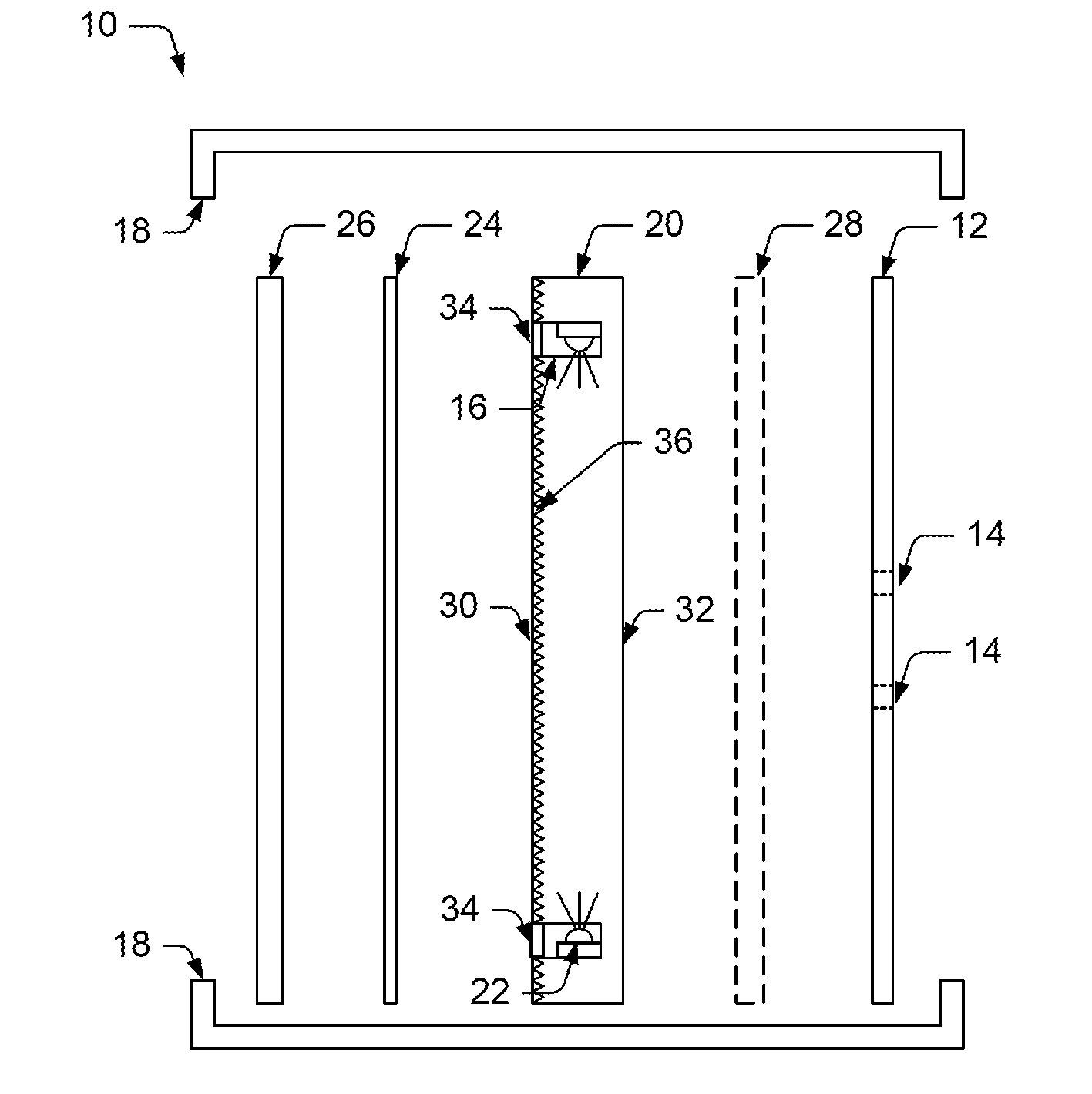
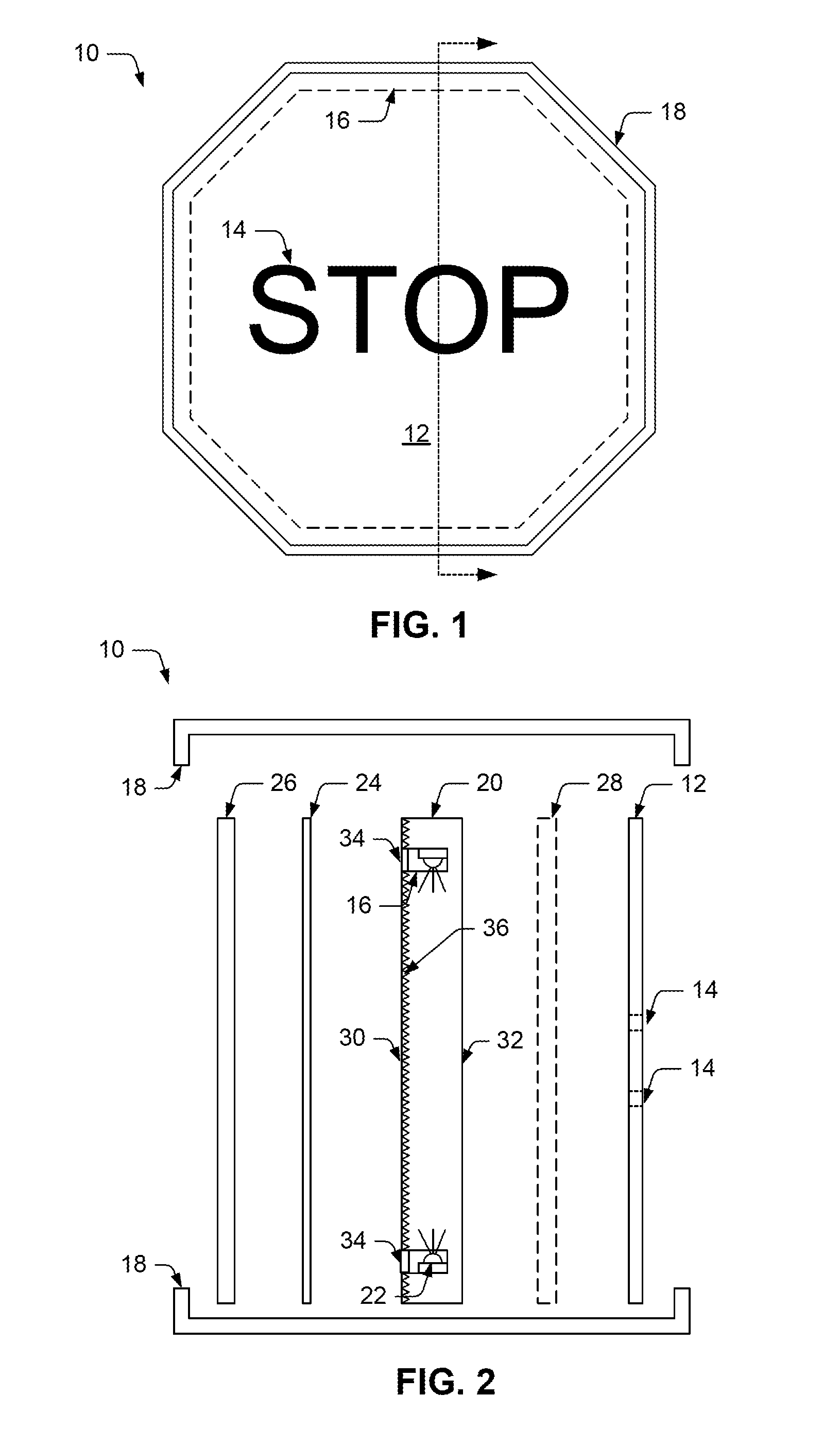
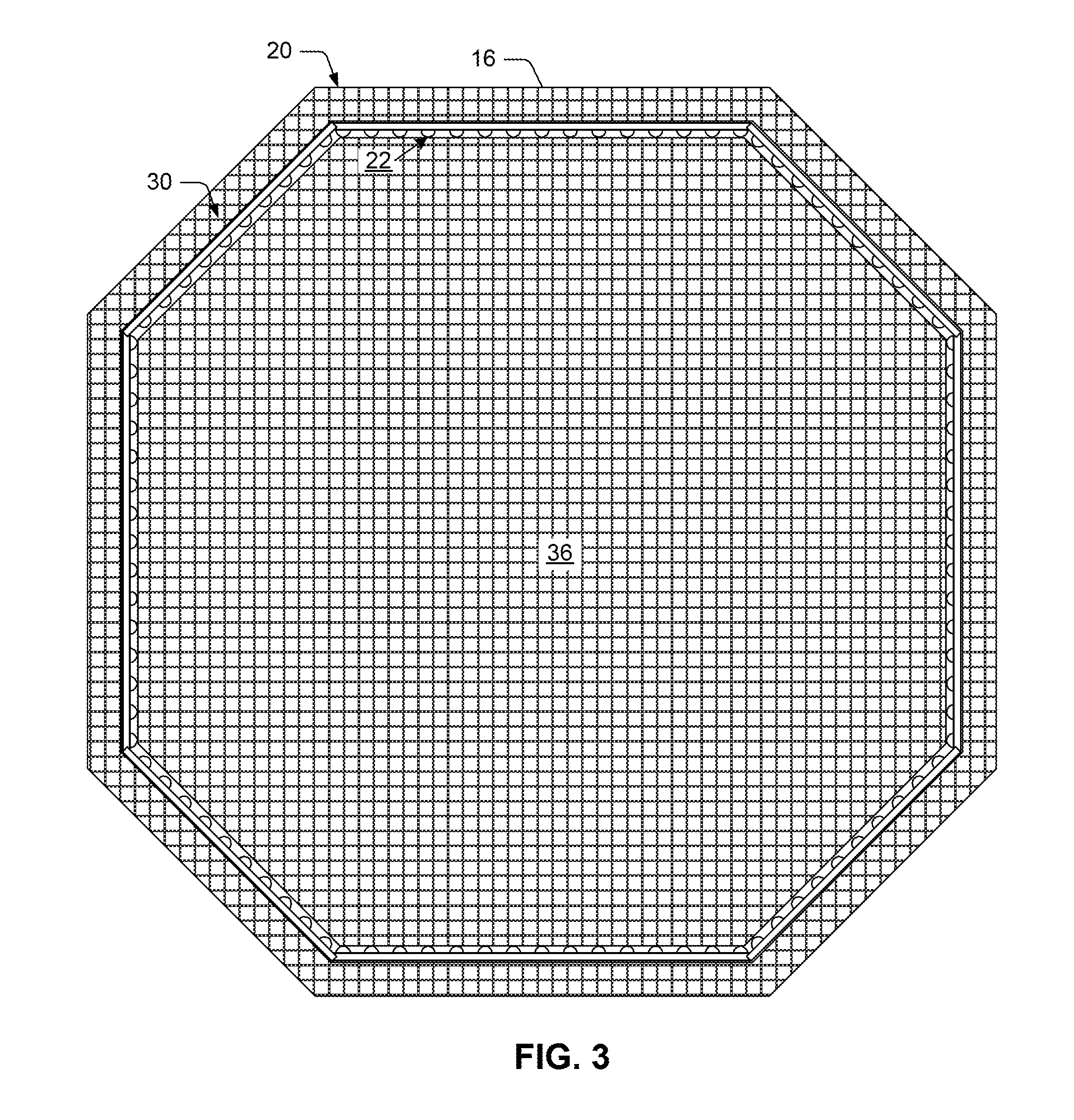
[0033]Turning now to the drawings, FIGS. 1-10 illustrate preferred embodiments of an internally illuminated panel, and methods for making such a panel, in accordance with the present invention. As will become apparent in the description set forth below, the preferred embodiments illustrated in FIGS. 1-10 improve upon conventional designs by providing uniform distribution and maximum intensity of the illumination emitted from the internally illuminated panel. In addition, means are provided for weatherproofing the panel and protecting the illumination source and circuitry embedded therein. Such means provide a highly rugged and robust design suitable for a variety of different environmental conditions, including indoor and outdoor applications.

[0034]As used herein, the term “internally illuminated panel” may be used to describe a wide variety of interior and exterior lighting devices including signs, decorative panels and other sources of illumination. Although aspects of the inventi...


PUM

PropertyMeasurementUnit
thicknessaaaaaaaaaa
thicknessaaaaaaaaaa
widthaaaaaaaaaa

Abstract

Embodiments of internally illuminated panels and methods for making such panels are disclosed herein. In general, the internally illuminated panel includes a transparent plate having a front surface and a back surface, a channel formed within the back surface of the transparent plate, and an illumination source embedded within the channel for directing illumination into an interior of the transparent plate. Unlike conventional panel designs, a pattern of grooves is formed across the back surface of the transparent plate for reflecting and refracting the internal illumination in a predetermined and predictable manner. In particular, characteristics of the pattern (such as the spacing and depth of the grooves) are configured to provide uniform distribution and intensity of the internal illumination emitted from the internally illuminated panel.

Description

BACKGROUND OF THE INVENTION[0001]1. Field of the Invention[0002]This invention relates to internally illuminated panels and, more particularly, to panels that are lit with internally embedded LEDs and have waterproofing features, which protect the panels from moisture. In one application, the internally illuminated panels may be implemented as traffic signs, road signs, advertising signs, billboards, store-front signs, signs indicating house / building / room numbers, etc. However, the internally illuminated panels described herein are not limited to signage, and may be applicable to many different indoor and outdoor lighting applications that would benefit from a uniformly lit panel, which is substantially impervious to moisture.[0003]2. Description of the Related Art[0004]The following descriptions and examples are given as background only.[0005]Illuminated signs are used in a wide variety of applications including, but not limited to, traffic signs, road signs, directional signs, adv...

Claims


Application Information

Patent Timeline
Patent Type & Authority Applications(United States)
IPC IPC(8): G09F13/18B23P19/04
CPCG09F13/14G09F13/18Y10T29/49888G09F13/0404G09F13/0413G09F13/22G09F2013/222G09F13/0422G09F13/0445G09F13/049Y10S362/812
Inventor RYUL, LEE SANG
Owner LEE SANG RYUL
Why Eureka
Try Eureka