Comminutor with screening conditioner

a technology of aminutor and a filter conditioner, which is applied in the direction of machines/engines, supporting apparatus, liquid fuel engines, etc., can solve the problems of material accumulation, difficult processing, and easy settling of wastewater treatment piping and equipment, so as to reduce the potential for accumulation, improve the effect of processing efficiency and reduce the potential for settling

Active Publication Date: 2012-02-16
GALANTY WILLIAM
View PDF0 Cites 12 Cited by
  • Summary
  • Abstract
  • Description
  • Claims
  • Application Information

AI Technical Summary

Benefits of technology

[0004]Certain embodiments of the present invention provide a comminutor screen for the size reduction of materials, including “flushable” wipes and similar products, which minimizes the potential for accumulation of rag-like and string-like solids in the comminutor or in downstream equipment. The screen provides a straight-through rotating comminutor design for more effective grinding, cleaner operation, and reduced maintenance. More particularly, stationary cutter bars are arrayed on the screen in such a manner as to avoid formation of gaps, ledges or transitions such that rag-like materials and stringy fragments have no place to wrap on the bar during grinding, Once reduced to sufficiently-small sizes, ground materials are carried cleanly through the screen slots. In some embodiments, gaps between the stationary cutter bars and side supports are spanned by tabs extending from the screen bars. This eliminates gaps on which rag-like or string-like solids might snag. The screen slots are fabricated to be smooth to prevent the formation of crevices on which solids might snag.

Problems solved by technology

Due to their high mechanical strength, these materials do not shred easily, and can readily become lodged in wastewater treatment piping and equipment.
Additionally, when subjected to the turbulent action of flow, these materials can be woven into large “mops,” further increasing their resistance to shredding, thereby making them even more difficult to process.
This impedes wastewater flow, and causes other operational difficulties in wastewater treatment facilities, necessitating downtime for digester clean-outs, de-ragging of pump impellers, and other maintenance.

Method used


Image

  • Comminutor with screening conditioner
  • Comminutor with screening conditioner
  • Comminutor with screening conditioner

Examples


Embodiment Construction

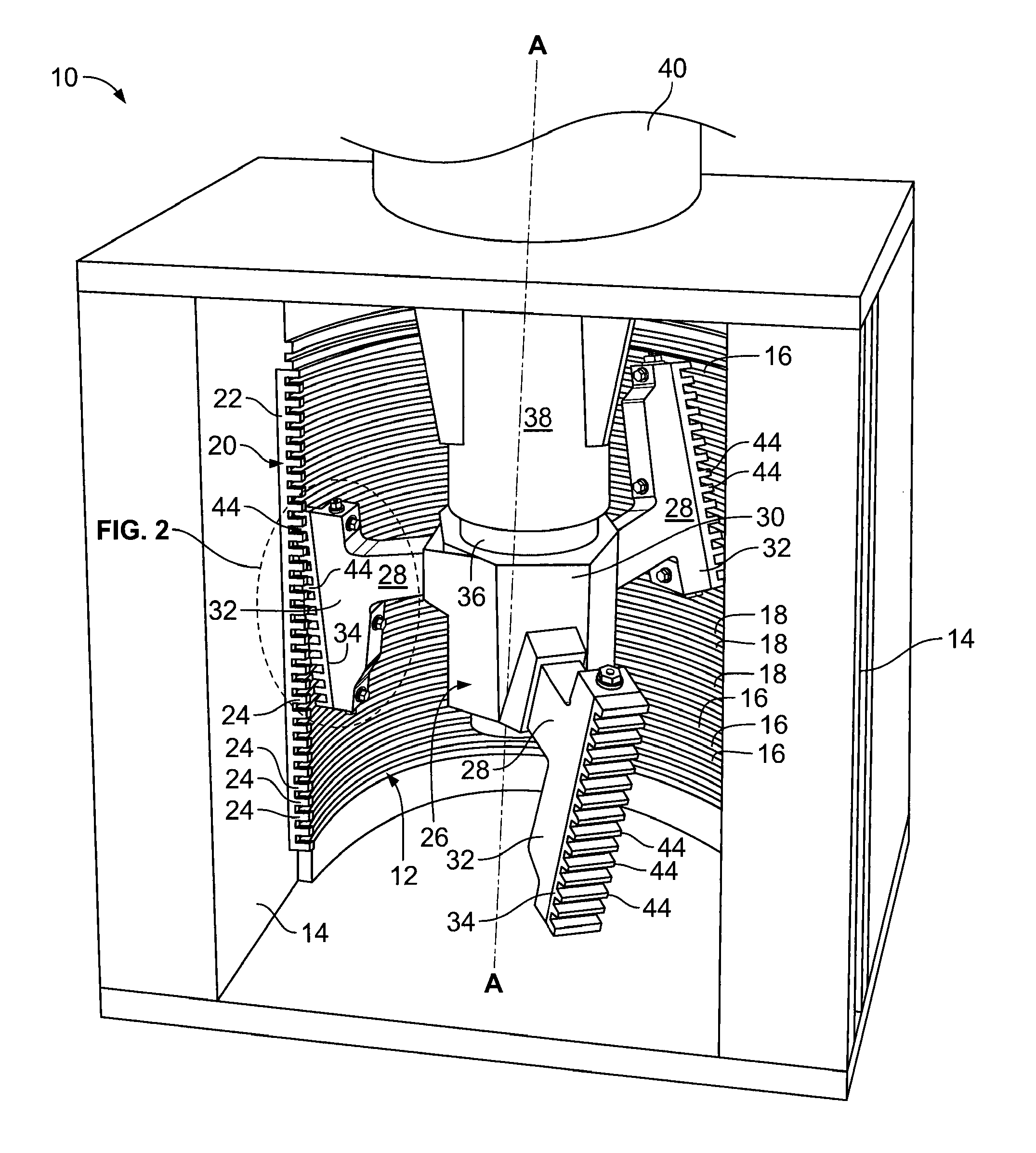
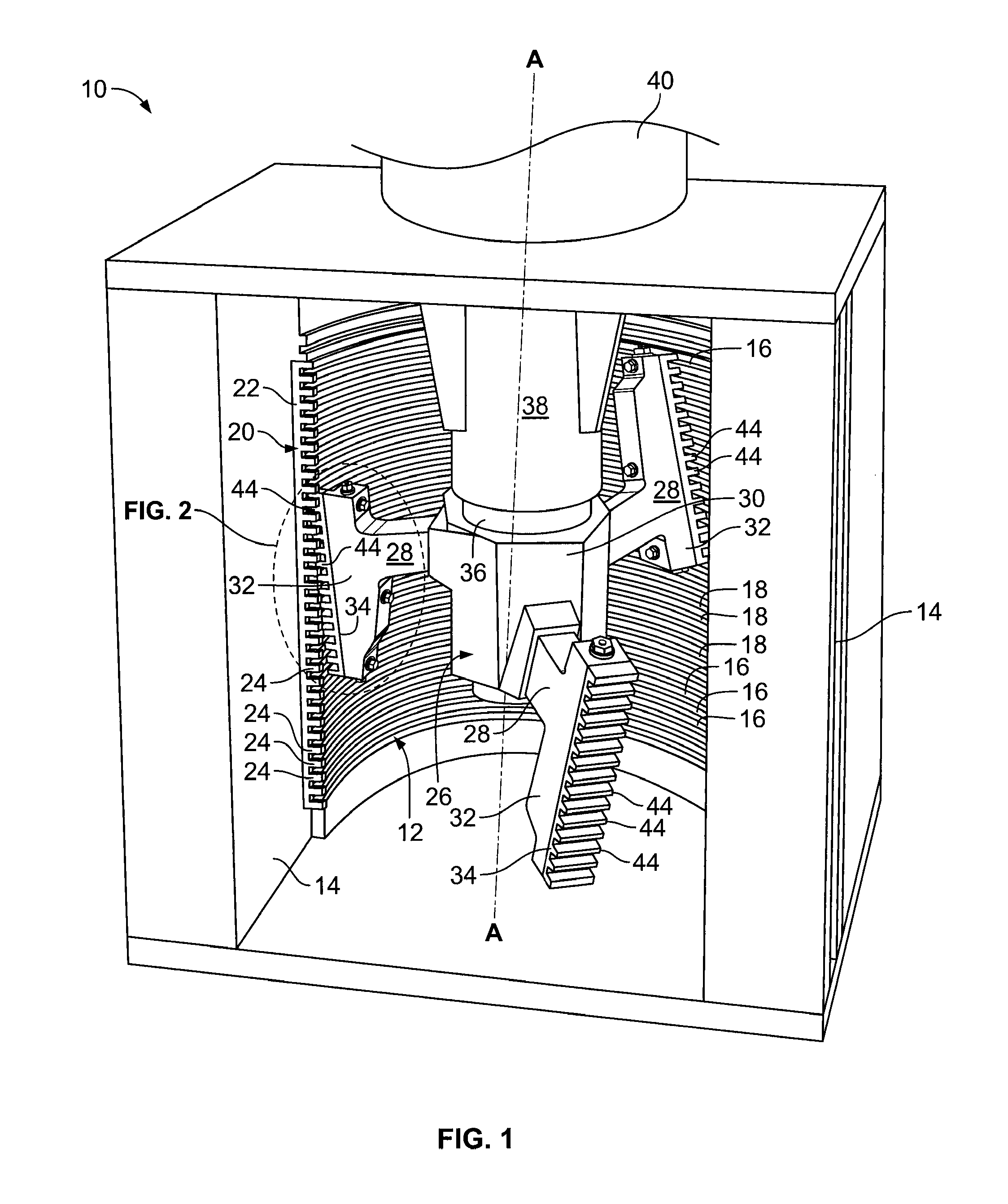
[0015]The present invention may be employed in a number of different types of comminutors having differing arrangements of fixed cages or screens for comminuting solid materials carried by liquid (e.g., sewage) flowing in an open channel. For example, the present invention is suitable for use in comminutors fabricated in accordance with the disclosures provided by U.S. Pat. No. 4,186,888 (“the '888 patent”), which is incorporated by reference herein in its entirety. The exemplary embodiments of the present invention presented herein are described in conjunction with a comminutor fabricated in accordance with the disclosures of the '888 patent.

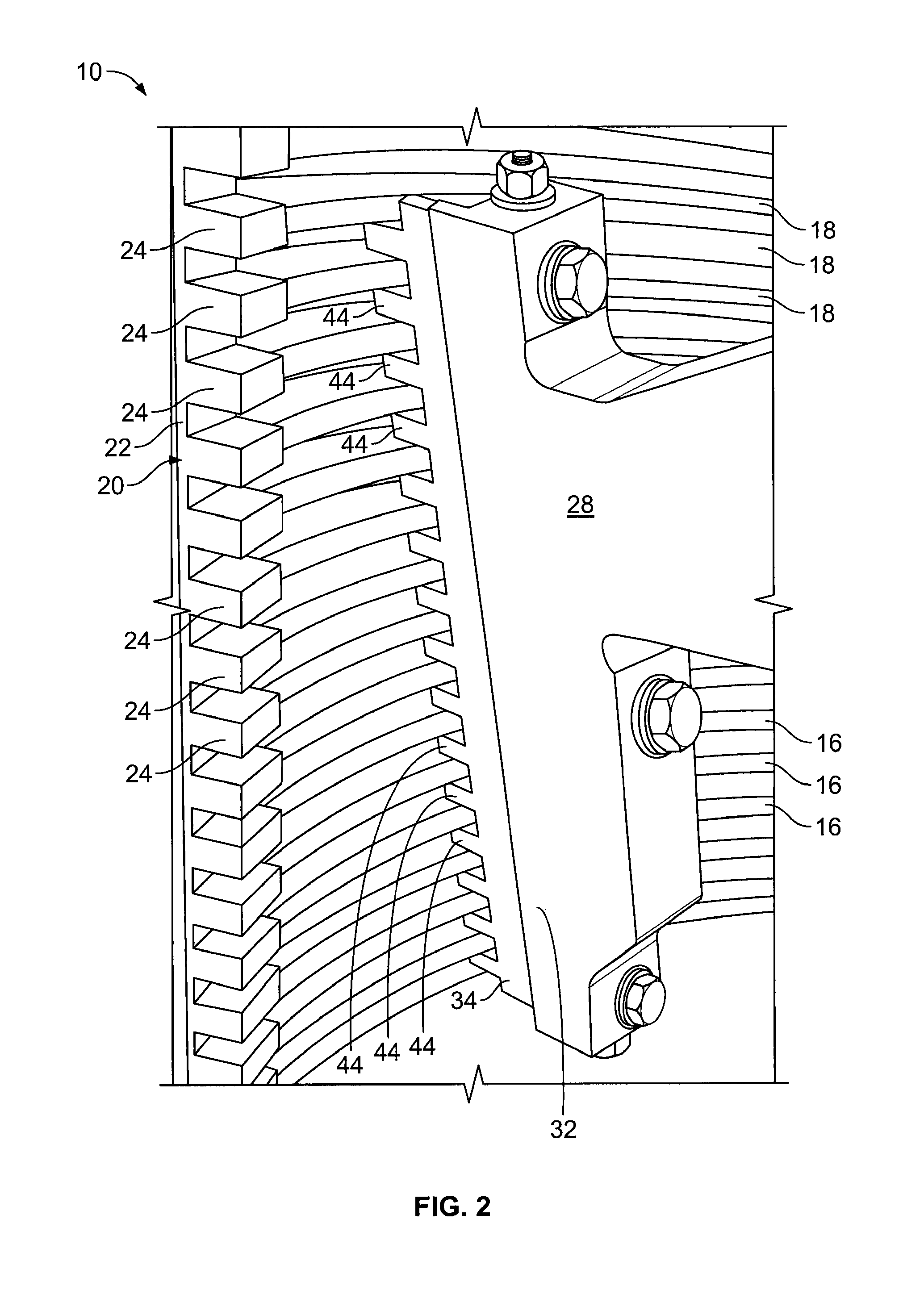
[0016]FIGS. 1 through 5 depict a comminutor 10 constructed in accordance with an exemplary embodiment of the present invention. Referring to jointly to FIGS. 1 and 2, the comminutor 10 includes a curved screen 12, concave toward the interior of the comminutor 10. In the present embodiment, the screen 12 has the shape of a semi-circular cylinder...


PUM


Abstract

A comminutor for shredding rag-like materials includes a frame member having a cutter bar that is affixed thereto and has a plurality of cutter teeth, and includes screen bars aligned with the cutter teeth. Each of the screen bars has an end that fits closely to its adjacent cutter tooth and the frame member so as to close a gap between the cutter tooth and the frame member. The end of the screen bar may include a flange that fits closely to the frame member and a tab proximate to the flange that fits closely to the cutter tooth. In an embodiment where the cutter tooth is flush with the frame member, the end of the screen bar includes a flange that fits closely to both frame member and the cutter tooth.

Description

CROSS-REFERENCE TO RELATED APPLICATION[0001]The present application claims priority from U.S. Provisional Patent Application No. 61 / 372,633, filed on Aug. 11, 2010.FIELD OF THE INVENTION[0002]The field of the invention relates to a comminutor for wastewater treatment, more particularly, to a comminutor for size reduction of rag-like and string-like solids in the waste stream.BACKGROUND OF THE INVENTION[0003]The recent introduction of “flushable” wipes and similar rag-like solids into sanitary waste streams in high volumes has had a severe impact on the operability of wastewater treatment systems, creating a need for improved methods of handling these new materials at such facilities. Due to their high mechanical strength, these materials do not shred easily, and can readily become lodged in wastewater treatment piping and equipment. Additionally, when subjected to the turbulent action of flow, these materials can be woven into large “mops,” further increasing their resistance to shr...

Claims


Application Information

Patent Timeline
Patent Type & Authority Applications(United States)
IPC IPC(8): B02C19/00
CPCB02C18/0092F04D7/045F04D29/2288
Inventor GALANTY, WILLIAM
Owner GALANTY WILLIAM
Why Eureka
Try Eureka