Method and apparatus for venting gas from liquid-conveying conduit

a technology of liquid-conveying conduit and gas venting method, which is applied in the direction of valve housing, functional valve type, transportation and packaging, etc., to achieve the effects of reducing wear rate, low melting point, and increasing the durability of anti-water-hammering

Inactive Publication Date: 2012-02-16
INT VALVE MFG
View PDF17 Cites 23 Cited by
  • Summary
  • Abstract
  • Description
  • Claims
  • Application Information

AI Technical Summary

Benefits of technology

[0012]The present invention further pertains to a method of increasing the durability of the anti-water-hammering (or anti-surge) components used in venting valves, which service pipelines with diameters 4 inches or greater. This is achieved by the use of annulus shaped inserts placed onto or into a valve member (or anti-surge) float to protect the discharge passageway / s by reducing the wear rate during high pressure gas discharge. The shape of the insert is not limited to that of an annulus and can include designs utilizing a wide array of internal hole shapes and external shape configurations that achieve the same objective.
[0013]The anti-surge valve components are typically composed of High Density Polyethylene (HDPE) or other light-weight materials that are soft and / or have low melting points. An unexpected benefit from using anti-wear inserts is that they provide a mechanism for distributing the heat load over a larger volume of the float (or valve member), which assists in managing the adverse impact of transient high temperature effects on the valve member cause by rapid adiabatic compression of the venting gas. The choice of material used to make the inserts can be either conducting or an insulation material like a ceramic; both have benefits in preventing the float material from melting under transient conditions.
[0014]Using components that better manage that brief period of elevated temperature is one way to increase the durability of the valve, however, slowing the flow of air through the valve when exceptionally high surge pressures are encountered is also useful, because it both decreases the heat load entering the valve and permits the hot gasses to shed the heat to the surrounding pipeline and liquid contents. Subsequently, a method to induce dynamic restriction of the gas flow is claimed, wherein the occurrence of exceptional high pressures will further limit the gas flow through the orifices of the anti-hammer valve member.

Problems solved by technology

The energetic conditions can generate liquid aerosols containing fine particles and also dislodge fine debris including rust particles from the surface of the pipeline and eject them at high velocity through the discharge orifices of the valve causing erosion.

Method used


Image

  • Method and apparatus for venting gas from liquid-conveying conduit
  • Method and apparatus for venting gas from liquid-conveying conduit
  • Method and apparatus for venting gas from liquid-conveying conduit

Examples


Embodiment Construction

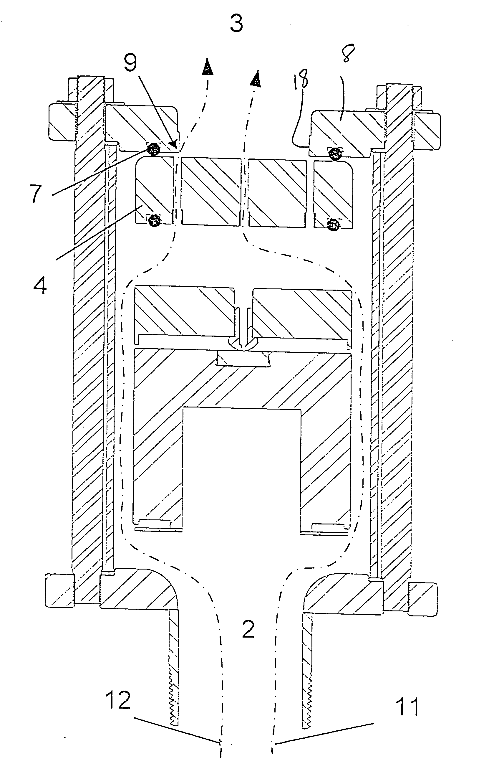
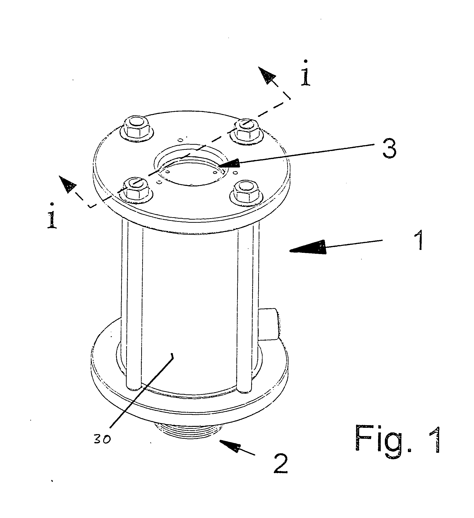
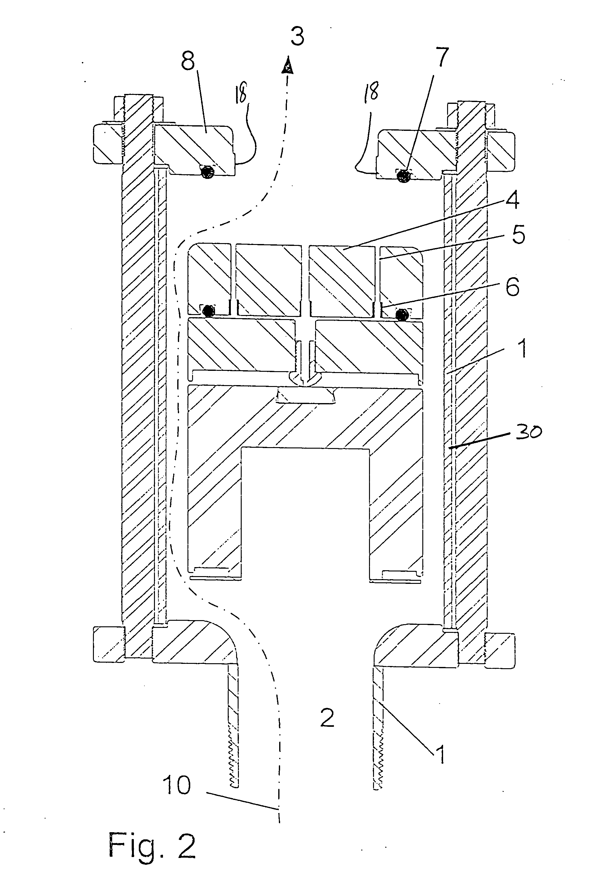
[0028]Referring now to the drawings with more specificity, the preferred embodiment of the present invention concerns a vent valve apparatus 1 as generally depicted in FIGS. 1-3, in which FIGS. 2 and 3 are longitudinal sectional views of the apparatus 1 otherwise perspectively depicted in FIG. 1. In this last regard, FIG. 2 is a longitudinal sectional view of the vent valve apparatus 1 according to the present invention depicting the structural configuration of internal components for venting gas when the vent valve apparatus is venting gas under low pressure and at flow rates typically less than 30 meters per second (via pathway 10) inletting at the apparatus inlet as referenced at 2, and exhausting to the apparatus outlet (as referenced at 3) via the outlet flange 8.

[0029]FIG. 3 is a longitudinal sectional view of the vent valve apparatus 1 according to the present invention depicting the structural configuration of internal components for venting gas when the vent valve apparatus...


PUM


Abstract

A valve-venting method increases the durability of flow restrictors within gas venting valves used on large diameter water and sewer pipelines such that transient high pressure conditions that can cause rapid adiabatic heating of the discharging gases are prevented from causing flow erosion and debris wear induced by the high velocities and thermal softening of the valve components. The method utilizes wear resistant orifice inserts that are more conductive than the valve component to better distribute the heat, and dynamic surge control geometry to slow the heat flow and provide progressive water-hammering control during high pressure events.

Description

BACKGROUND OF THE INVENTION[0001]1. Field of the Invention[0002]The present invention generally relates to valves and valve methodology. More particularly, the present invention relates to a valve-based apparatus and method for use with large diameter water and sewerage pipelines to provide controlled means for allowing gases to be released when the pipeline is pressurized or filled, and to allow air to enter into the pipeline when the internal pressure of the pipeline drops below atmospheric pressure.[0003]2. Brief Description of the Prior Art[0004]Large pipelines that supply water or transport sewerage often transverse undulating terrain. This is one reason why the proper operation of these pipelines requires the removal of air pockets that may form during operation or during the filling process. Similarly, pipelines occasionally experience negative pressures that may be due to emptying, pumping disruptions, and maintenance or failure conditions. Regardless of the reason, large di...

Claims


Application Information

Patent Timeline
Patent Type & Authority Applications(United States)
IPC IPC(8): F16K24/04F16K27/00
CPCE03F5/08F16K24/044Y10T137/3099
Inventor LANG, III, RUDOLPH J.WITHERIDGE, ANTHONY JOHN
Owner INT VALVE MFG
Why Eureka
Try Eureka