Suspension arm for a motor vehicle wheel suspension and method for manufacturing same

a technology for suspension arms and motor vehicles, which is applied in the direction of resilient suspensions, metal-working apparatus, vehicle components, etc., can solve the problems of increasing the weight of the arm relative to the open-section stamped arm, increasing the cost of the arm, etc., and minimizing the overall cost and weight of the arm. , the effect of increasing the stiffness and mechanical strength

Active Publication Date: 2012-02-16
SISTEMI SOSPENSIONI SPA
View PDF12 Cites 7 Cited by
  • Summary
  • Abstract
  • Description
  • Claims
  • Application Information

AI Technical Summary

Benefits of technology

[0009]The invention is based on the idea of providing a swing arm for a vehicle suspension, in particular for a front suspension, in which at least one secondary arm portion having a closed section is obtained by folding and firmly securing, such as by welding, a strip of sheet metal to the remaining main arm portion having an open section. A reinforcement is thus obtained which is located in the zone(s) of the arm where it is necessary to increase the stiffness and the mechanical strength, thereby minimizing the overall cost and weight of the arm.

Problems solved by technology

The swing arm known from the aforesaid patent is manufactured by folding of the edge zones of the arm substantially along the whole perimeter of the same, with the exception of the zone of mounting of the wheel and of the zone of connection to the vehicle body, as well as of the zone of bifurcation of the transversely inner arm portion, which causes an increase in the cost of the arm, in addition to an increase in the weight of the arm with respect to an open-section stamped arm.

Method used


Image

  • Suspension arm for a motor vehicle wheel suspension and method for manufacturing same
  • Suspension arm for a motor vehicle wheel suspension and method for manufacturing same
  • Suspension arm for a motor vehicle wheel suspension and method for manufacturing same

Examples


Embodiment Construction

[0016]In the following description and claims, terms such as “longitudinal” and “transverse,”“inner” and “outer,” and “front” and “rear” are referred to the mounted condition of the swing arm on the vehicle—in particular, to the mounted condition of the swing arm as a component of the front suspension of the vehicle.

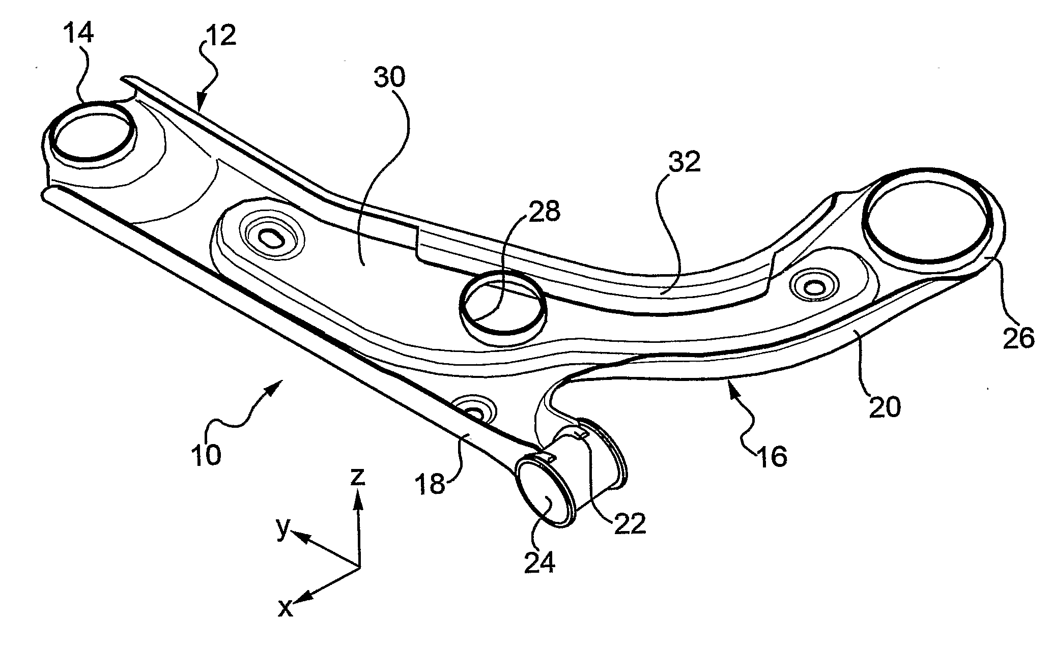
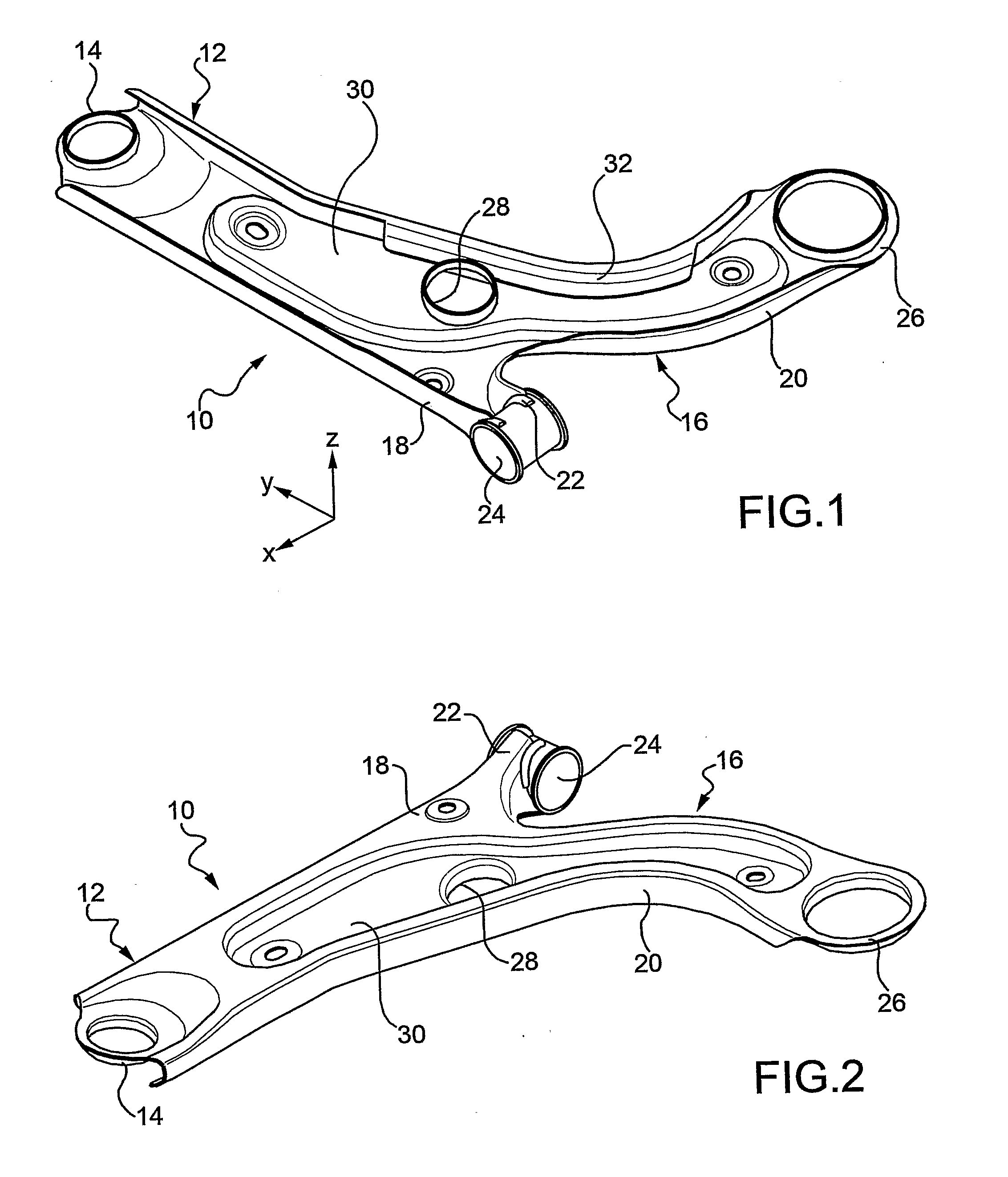
[0017]With reference first to FIGS. 1 and 2, a swing arm according to an embodiment of the invention is generally indicated 10 and integrally forms a transversely outer arm portion 12 extending substantially in the transverse direction of the vehicle (direction “y” of the “x-y-z” reference system indicated in FIG. 1) and having a free end 14 for mounting of a support (not illustrated) for supporting a vehicle wheel and a transversely inner arm portion 16 with a first branch 18 and second branch 20 bifurcating from the transversely outer arm portion 12. The first branch 18 is substantially aligned (transverse direction “y”) with the transversely outer arm portion 12 and h...


PUM

PropertyMeasurementUnit
straight lengthsaaaaaaaaaa
lengthaaaaaaaaaa
lengthsaaaaaaaaaa

Abstract

A swing arm for a suspension of a vehicle comprises a substantially transversely outer arm portion having a free end for mounting of a support for supporting a wheel of the vehicle and a substantially transversely inner arm portion with a first branch and second branch. The first branch is substantially aligned with the outer arm portion and has a free end for mounting of a first connector for connection to a body of the vehicle, and the second branch extends along an arched path towards a rear part of the vehicle and has a free end for mounting of a second connector for connection to the vehicle body. A single-sheet metal piece includes a main portion having an open section and at least one secondary portion arranged in an edge zone of the swing arm, having a closed section, and formed by at least one strip of the metal piece folded onto the main portion and firmly secured with a free edge of the strip to the main portion. A method for manufacturing the swing arm comprises steps of obtaining the main portion by stamping of the metal piece, folding the strip of the metal piece so as to obtain the secondary portion, and firmly securing the free edge of the strip to the main portion.

Description

CROSS-REFERENCE TO RELATED APPLICATIONS[0001]This application claims benefit of PCT Patent Application PCT / IB2010 / 050513 entitled “Suspension Arm for a Motor Vehicle Wheel Suspension” and filed on Feb. 4, 2010, which claims benefit of Italian Patent Application TO2009A000076 filed on Feb. 5, 2009.BACKGROUND OF INVENTION[0002]1. Field of Invention[0003]The invention relates, generally, to a swing arm for a vehicle suspension and, in particular, to a swing arm for a vehicle front suspension as well as a method for manufacturing such an arm.[0004]2. Description of Related Art[0005]A swing arm of the above-indicated type is known from European Patent EP0794075B1. According to this known solution, the swing arm is obtained by stamping from a single sheet metal piece including a main portion which has an open section and secondary portions which have a closed section and are arranged along edge zones of the arm. The swing arm known from the aforesaid patent is manufactured by folding of t...

Claims


Application Information

Patent Timeline
Patent Type & Authority Applications(United States)
IPC IPC(8): B60G3/16B23P15/00
CPCB60G7/001B60G2206/122B60G2206/8102B60G2206/8201Y10T29/49622
Inventor MONCHIERO, PIEROLO GIUDICE, STEFANO
Owner SISTEMI SOSPENSIONI SPA
Why Eureka
Try Eureka