Electro-optic device and electronic apparatus

a technology of electronic equipment and optical devices, applied in the field of image display, can solve the problems of increasing difficulty in ensuring a sufficient time length of writing time, etc., and achieve the effect of reducing circuit size or power consumption, and preventing writing shortage of gray scale potential

Active Publication Date: 2012-02-16
SEIKO EPSON CORP
View PDF20 Cites 5 Cited by
  • Summary
  • Abstract
  • Description
  • Claims
  • Application Information

AI Technical Summary

Benefits of technology

[0006]An advantage of some aspects of the invention is that it provides a technique for preventing writing s

Problems solved by technology

Therefore, it is difficult to ensure a sufficient time length of the writing time.

Method used


Image

  • Electro-optic device and electronic apparatus
  • Electro-optic device and electronic apparatus
  • Electro-optic device and electronic apparatus

Examples


first embodiment

A. First Embodiment

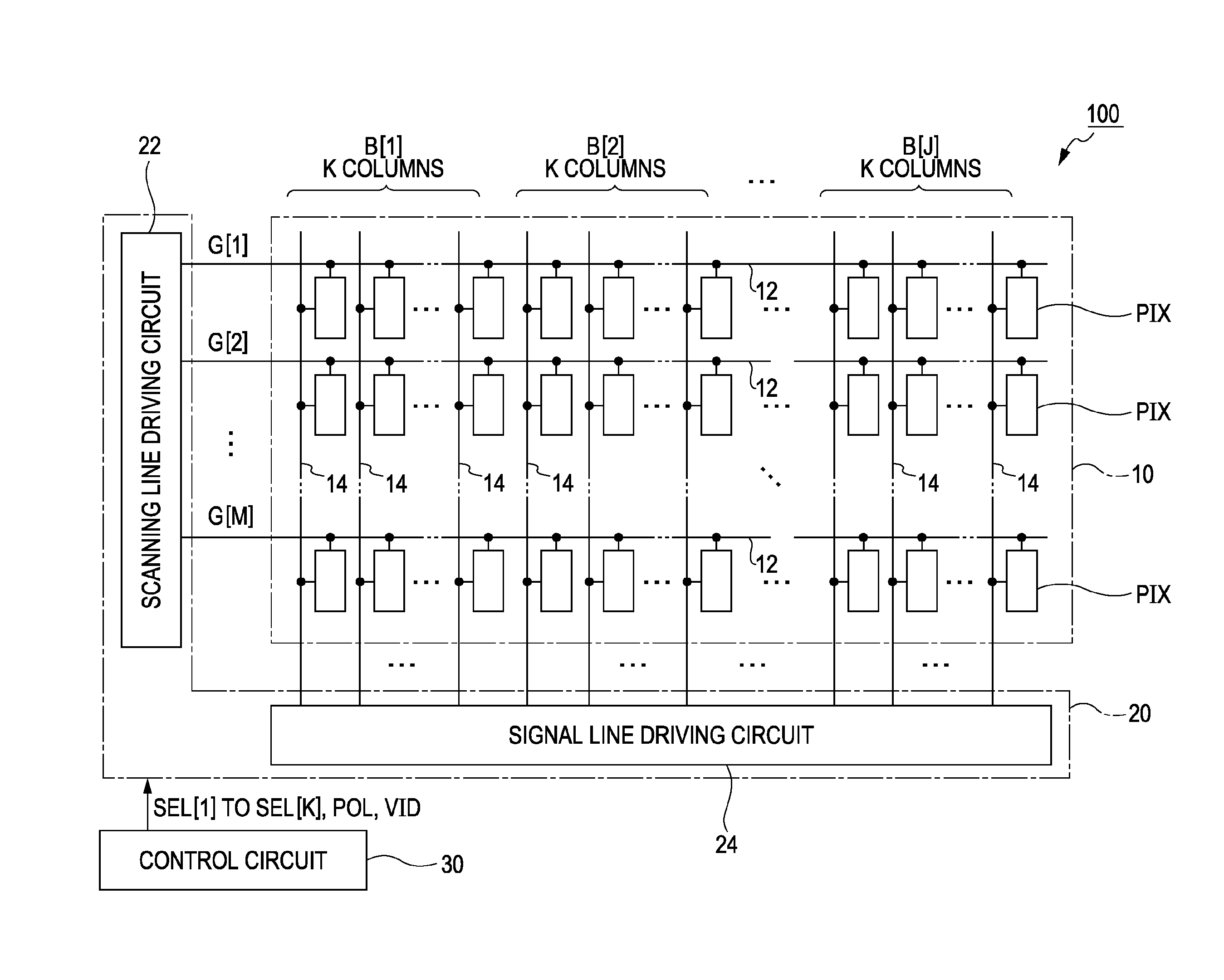
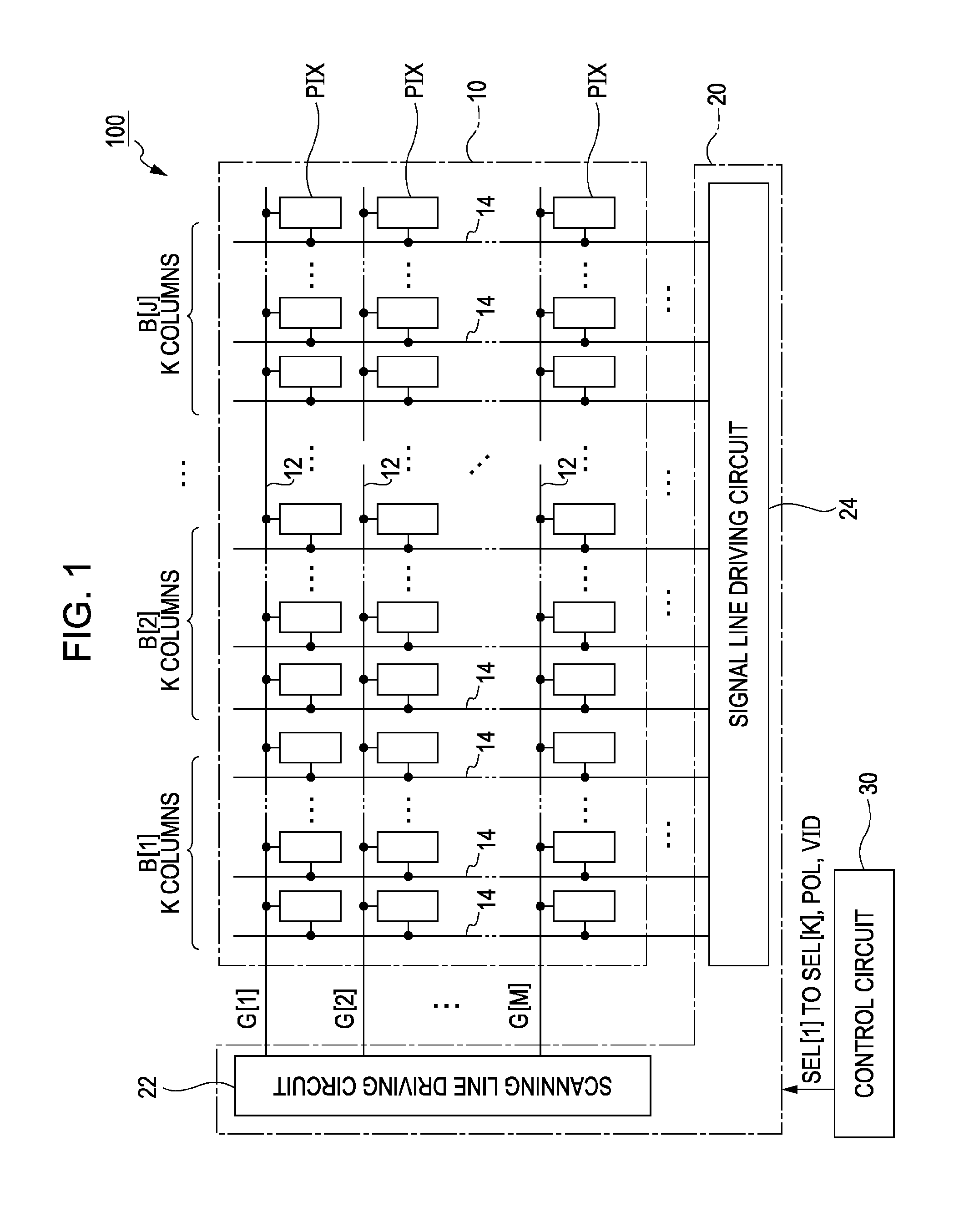
[0020]FIG. 1 is a block diagram illustrating an electro-optic device 100 according to a first embodiment of the invention. The electro-optic device 100 is a liquid crystal device that is mounted as a display device displaying an image on various electronic apparatuses. As shown in FIG. 1, the electric-optic device 100 includes a pixel section 10 in which a plurality of pixel circuits PIX is arranged in a planar surface, a driving circuit 20 which drives the respective pixel circuits PIX, and a control circuit 30 which controls the driving circuit 20. The driving circuit 20 includes a scanning line driving circuit 22 and a signal line driving circuit 24.

[0021]In the pixel section 10, M (where M is a natural number) scanning lines 12 and N (where N is a natural number) signal lines 14 intersecting each other are formed. In the pixel section 10, the N signal lines 14 are divided into J wiring groups (blocks) B[1] to B[J] in units of K (where K is a natural number of ...

second embodiment

B. Second Embodiment

[0034]Next, a second embodiment of the invention will be described. The same reference numerals are given to the constituent elements having the same operations and functions as those of the first embodiment and the description thereof will not be repeated.

[0035]FIG. 5 is a diagram illustrating an operation of an electro-optic device 100 according to the second embodiment. As shown in FIG. 5, a variation δ (VPRE→VG) in the potential of the signal line 14 after elapse of the precharge period TPRE is considerably lower in a case (the vertical scanning period V2), where the gray scale potential VG and the precharge potential VPRE during the writing period TWRT has a reverse polarity with respect to the reference potential VREF, than in a case (the vertical scanning period V1), where the gray scale potential VG and the precharge potential VPRE during the writing period TWRT has the same polarity with respect to the reference potential VREF. In the second embodiment, ...

modification 1

(1) Modification 1

[0039]The precharge potential VPRE is appropriately modified. For example, the precharge potential VPRE may be set as the positive polarity potential with respect to the reference potential VREF. Alternatively, the precharge potential VPRE may be varied in accordance with the polarity (the polarity signal POL) of the gray scale potential VG (where the precharge potential VPRE is different between the vertical scanning period V1 and the vertical scanning period V2).


PUM


Abstract

A signal supply circuit supplies, to a control line, a control signal which is set so as to have a precharge potential during a precharge period before start of a writing period and which is set so as to have a gray scale potential corresponding to a designated gray scale of each pixel in a time division manner during the writing period. A plurality of switches controls connection between the signal lines and the control line. A control circuit controls the plurality of switches so as to be concurrently turned on during a precharge period and controls the plurality of switches so as to be turned on sequentially during a plurality of unit periods of the writing period. The control circuit sets an initial unit period after elapse of the precharge period among the plurality of unit periods so as to be longer than the other unit periods.

Description

BACKGROUND[0001]1. Technical Field[0002]The present invention relates to a technique for displaying an image using an electro-optic element such as a liquid crystal element.[0003]2. Related Art[0004]Hitherto, there has been suggested an electro-optic device in which pixel circuits are arranged in a matrix form so as to correspond to intersections of a plurality of scanning lines and a plurality of signal lines, respectively. JP-A-2009-116247 discloses a configuration in which a plurality of signal lines is divided into a plurality of sets (hereinafter, referred to as “wiring groups”) in units of a predetermined number, a predetermined precharge potential is concurrently supplied to the signal lines of each set, and a gray scale potential corresponding to a designated gray scale of each pixel circuit is supplied to the respective signal lines of each wiring group in a time division manner during each writing period.[0005]In the configuration disclosed in JP-A-2009-116247, a case (her...

Claims


Application Information

Patent Timeline
IPC IPC(8): G09G5/02
CPCG09G3/20G09G3/36G09G2310/0251G09G2310/0297G09G2320/0252
Inventor ITO, AKIHIKO
Owner SEIKO EPSON CORP
Why Eureka
Try Eureka