Measuring apparatus and measuring method thereof, apparatus for correcting processing position of cutting machine and method thereof for correcting processing position, and imaging apparatus and cutting machine comprising the same

a technology of measuring apparatus and measuring method, which is applied in the direction of heat measurement, instruments, television systems, etc., can solve the problems of inability to perform useless operations in such cases, and achieve the effect of accurate measurement, high accuracy and simplified configuration of measuring apparatus

Active Publication Date: 2012-02-16
FUJI CORP
View PDF11 Cites 28 Cited by
  • Summary
  • Abstract
  • Description
  • Claims
  • Application Information

AI Technical Summary

Benefits of technology

[0016]The measuring apparatus and the measuring method thereof according to the present invention image, as a subject, a reference body which is a reference of a heat displacement amount of a heat-displaced object to be measured in a same imaging area in an imaging means, collates reference image data at a reference temperature, which has been recorded in advance in a recording means, with measured image data at a time of an arbitrary measurement by a collating means, and measures a temperature of the object to be measured at a time of an arbitrary measurement based on a collation result by the collating means, and therefore can accurately measure the temperature of the object to be measured. In addition, the temperature of the object to be measured can be measured from a distant point in a noncontact state without any connection by wiring or the like, so that the need of a member for a wiring connection, for example, a brush holder can be eliminated, and that the configuration of measuring apparatus can be simplified.
[0017]The apparatus for correcting a processing position of a cutting machine and the method for correcting a processing position thereof according to the present invention establish correspondences between a reference gauge (arranged on a chuck) for measuring a position error of an imaging means and a reference means which is arranged on a mounting table in order to detect a displacement amount of a (displaced or deficient) cutting tool and a temperature of the mounting table of the cutting tool, images, as a subject of the imaging means, the corresponding reference gauge and the corresponding reference means in a same imaging area in the imaging means, collates reference image data at a reference temperature, which has been recorded in advance in a recording means, with measured image data at a time of an arbitrary measurement by a collating means, and corrects a processing position of the cutting tool based on a collation result by the collating means, so as to, for example at a time of not cutting during an operation, correct a processing position by calculating a temperature of a feed mechanism of amounting table or the like (ball screw mechanism or the like) and a displacement amount of the cutting tool. Therefore, even if a processing position is displaced due to the thermal expansion / contraction of the feed mechanism during the operation, the displacement of the processing position thereof can be corrected with high accuracy, and processing accuracy of a workpiece can be improved.
[0018]Furthermore, the apparatus for correcting a processing position of a cutting machine and the method for correcting a processing position thereof according to the present invention establishes correspondence between a reference gauge which is arranged on a chuck for holding a workpiece in order to measure a position error of an imaging means, and a reference body which is a reference of a heat displacement amount of the reference gauge, and which is arranged in such a manner that one end is fixed to the chuck and a free end corresponds to the reference gauge, images, as a subject of the imaging means, the corresponding reference gauge and the corresponding free end of the reference body in a same imaging area in the imaging means, collates reference image data at a reference temperature, which has been recorded in advance in a recording means, with measured image data at a time of an arbitrary measurement by a collating means, and corrects a reference position of a cutting tool based on a collation result by the collating means. Therefore, even if a processing position is displaced due to the thermal expansion / contraction of the chuck, the displacement of the processing position thereof can be corrected with high accuracy, and processing accuracy of a workpiece can be improved.
[0019]Furthermore, the imaging apparatus or the cutting machine comprising this imaging apparatus according to the present invention respectively opens and closes each shutter in a time considered to be a moment (time difference in switching optical paths), so that there is no variation between positions of subjects at the time of imaging, and that subjects at different imaging positions can be imaged in a state which can be substantially considered as viewing the whole thereof. More specifically, according to the imaging apparatus or the cutting machine comprising this imaging apparatus according to the present invention, for example, five million pixels (size of 17 mm in a short side and 21.5 mm in a long side) can be effectively used as they are without reducing an imaging area of the imaging apparatus by, for example, dividing, so that image recognition can be improved. Furthermore, according to the imaging apparatus or the cutting machine comprising this imaging apparatus according to the present invention, a subject at a different imaging position, such as an inner diameter tool bit or an outer diameter tool bit, can be imaged respectively, so that a type of a tool bit, such as an inner diameter tool bit, an outer diameter tool bit or other special tool bits, can be imaged in a state which can be substantially considered as viewing the whole thereof, without separately providing, for example, a reference gauge for an inner diameter tool bit. Furthermore, according to the imaging apparatus or the cutting machine comprising this imaging apparatus according to the present invention, a subject at a different imaging position can be imaged respectively, so that for example a travel amount of the cutting tool can be reduced, and that a moving mechanism f the cutting tool can be downsized.

Problems solved by technology

That is, useless operations are to be done in such a case.

Method used


Image

  • Measuring apparatus and measuring method thereof, apparatus for correcting processing position of cutting machine and method thereof for correcting processing position, and imaging apparatus and cutting machine comprising the same
  • Measuring apparatus and measuring method thereof, apparatus for correcting processing position of cutting machine and method thereof for correcting processing position, and imaging apparatus and cutting machine comprising the same
  • Measuring apparatus and measuring method thereof, apparatus for correcting processing position of cutting machine and method thereof for correcting processing position, and imaging apparatus and cutting machine comprising the same

Examples


first embodiment

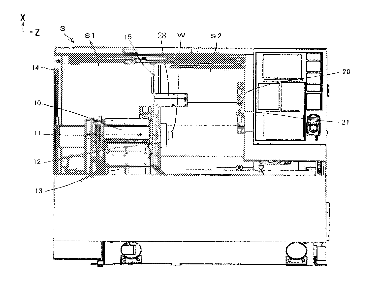
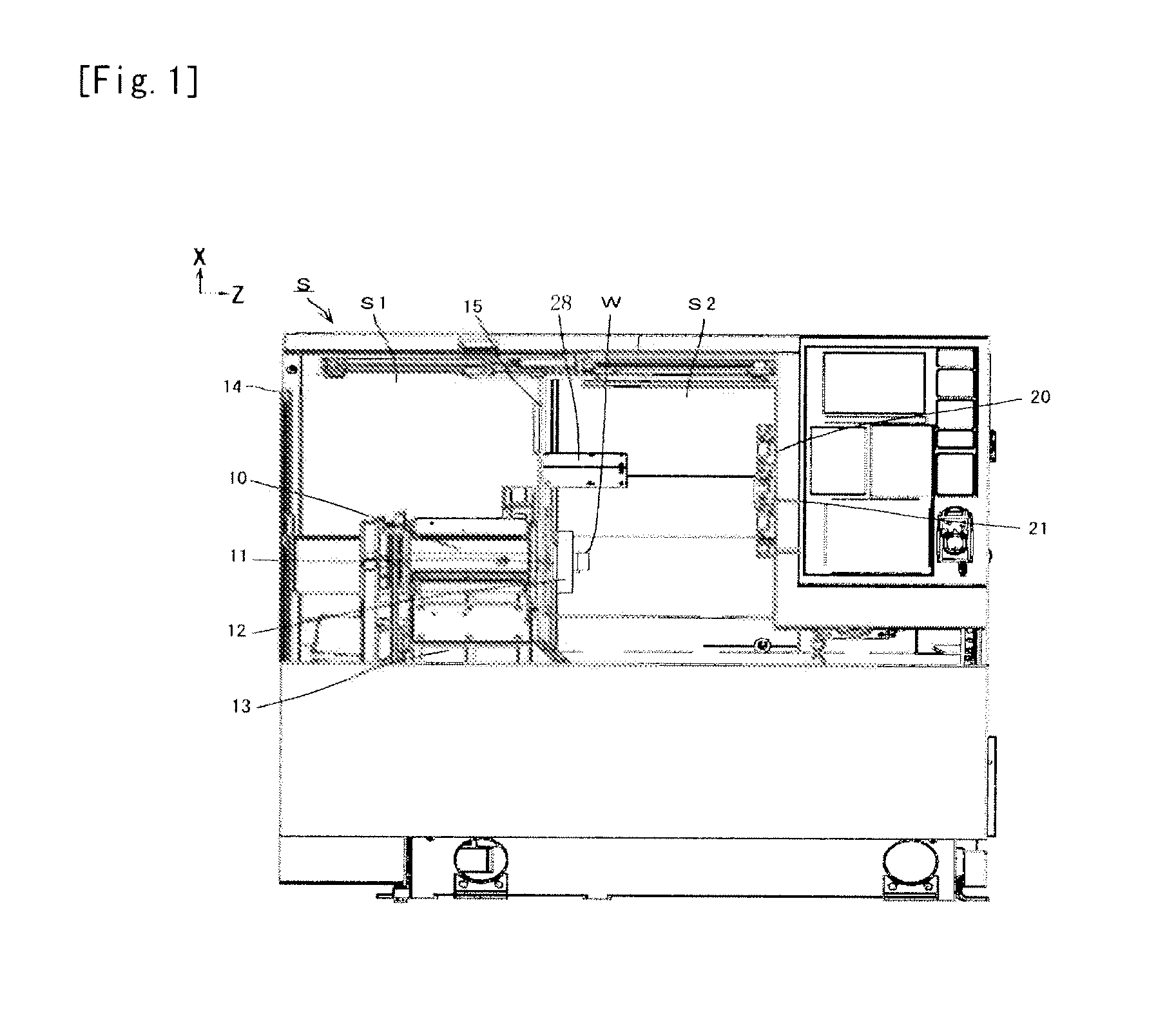
[0069]Hereinafter, a measuring apparatus and an apparatus for correcting a processing position of a cutting machine which is provided with the measuring apparatus, as well as a measuring method and a method for correcting a processing position of a cutting machine which uses the measuring method, which are first embodiment of the present invention, will be described based on FIG. 1 to FIG. 13. It should be noted that a cutting machine according to first embodiment will be described as a single-spindle turret lathe (hereinafter, simply referred to as lathe) S.

(Schematic Configuration of Lathe S)

[0070]As illustrated in FIG. 1, in a lathe S, a headstock 10 which is fixed in such a manner that an axis line thereof is parallel to a Z-axis direction (horizontal direction), and a turret apparatus 20 which is movable in a direction parallel to the Z-axis direction and a direction parallel to an X-axis direction, which is inclined rearward at an angle of 60 with respect to a vertical directi...

second embodiment

[0118]Second embodiment of the present invention will be described using FIGS. 20 to 24. However, substantially the same parts as those in the above-mentioned first embodiment are denoted by the same reference signs to omit or simplify the explanation thereof, and different parts will be mainly described. Second embodiment is an example applied to a double-spindle face lathe as illustrated in FIG. 20. In particular, two main spindles 11 are provided so as to lie on the right side and the left side and extend horizontally and in parallel to each other, and a chuck 12 for holding a workpiece is provided at the anterior end of each main spindle 11. Tool posts 21 are arranged, in parallel to an axis line of each main spindle 11, at a position on the left side and a position on the right side of the right and left main spindles 11, respectively. Each of the tool posts 21 is configured so as to be movable in an anteroposterior direction and rotatable around a shaft center of the tool post...

third embodiment

[0122]Third embodiment of the present invention will be described using FIGS. 26 to 28. However, substantially the same parts as those in the above-mentioned first embodiment are denoted by the same reference signs to omit or simplify the explanation thereof, and different parts will be mainly described. In third embodiment, as illustrated in FIG. 26, the invar body 47 which is a chuck gauge is arranged on the outer periphery side of the chuck 12 so as to be capable of viewing the whole of the reference gauge 18 and the leading edge 47A of the invar body 47. The invar body 47 (also referred to as chuck gauge in third embodiment) has one end thereof fixed by a pair of bolts 49A through a check plate 49B. Therefore, a stopper 72 for preventing jumping out is arranged on a free end side of the invar body 47 in a state of being slightly separated from the invar body 47. In addition, a counterweight 70 for preventing vibration is arranged on the opposite side of the arrangement position ...


PUM

PropertyMeasurementUnit
sizeaaaaaaaaaa
sizeaaaaaaaaaa
air pressureaaaaaaaaaa

Abstract

Provided is an apparatus and a method thereof which can detect a displacement amount of a cutting tool with respect to a workpiece with high accuracy and can correct a processing position with high accuracy. Accordingly, a turret gauge 46 is comprised of an invar body 47 and a gauge main body 48 with a different thermal expansion coefficient. A point A of the gauge main body 48 and a leading edge 47A of the invar body are imaged in a state of viewing the whole thereof at a time of an initialization and a calibration cycle (CS), and a temperature of the gauge main body 48 is detected by comparing each image data. Furthermore, the length between the point A and a point B of the gauge main body 48 at the time of the CS is obtained based on the image data. The actual length is compared with a theoretical length between the point A and the point B at a temperature of the gauge main body 48 at the time of the CS, and consideration is given to the comparison. Therefore, a heat displacement amount of a ball screw can be accurately detected, the displacement of a processing position of a cutting tool can be corrected with high accuracy, and processing accuracy of a workpiece can be improved.

Description

TECHNICAL FIELD[0001]The present invention relates to a measuring apparatus for measuring a displacement amount of a cutting tool by processing an image of an object to be measured, such as a cutting tool, and a measuring method thereof, and to an apparatus for correcting a processing position of a cutting machine and a method thereof for correcting the processing position. Furthermore, the present invention constitutes a part of the above-mentioned apparatus for correcting a processing position, and relates to an imaging apparatus for respectively imaging a plurality of subjects at substantially the same time, and a cutting machine for detecting a state of a cutting tool by imaging the cutting tool or the like by the said imaging apparatus.BACKGROUND ART[0002]For example, Patent Literature 1 discloses a measuring apparatus for measuring an expansion coefficient or the like of a sample whose expansion coefficient or contraction coefficient is unclear, based on an amount of change of...

Claims


Application Information

Patent Timeline
Patent Type & Authority Applications(United States)
IPC IPC(8): H04N7/18B26D5/20H04N5/225
CPCB23B25/06B23Q11/0003B23Q17/09B23Q17/0928B23Q17/20G01K5/50G01K2217/00B23Q17/2495G01N21/86H04N7/18Y10T83/162B23Q17/0909B23Q17/0985B23Q17/249
Inventor KAWADA, TOSUKEKATO, MASAKIICHINO, SHINJI
Owner FUJI CORP
Why Eureka
Try Eureka