Barrier for thin film lithium batteries made on flexible substrates and related methods

Active Publication Date: 2012-02-16
SAKTI3
View PDF4 Cites 76 Cited by
  • Summary
  • Abstract
  • Description
  • Claims
  • Application Information

AI Technical Summary

Benefits of technology

[0007]In a solid-state battery, the electrochemical reactions occur between a cathode and an anode through a solid electrolyte layer that is electrically insulating and ionically conductive. This construction of thin films layers differentiates solid-state batteries from conventional liquid electrolyte based batteries, with higher energy and power densities and longer cycle life due to more efficient material usage and homogeneous charge, strain and heat distribution.
[0011]In a specific embodiment, the present invention provides a method for fabricating a solid-state battery device. The method includes providing a substrate having a surface region. The method includes forming a bottom thin film barrier material overlying and directly contacting the surface region of the substrate. Preferably, the bottom thin film barrier material is configured to prevent ionic species from a first anode material to migrate to the substrate. The method includes forming a first current collector region overlying the bottom barrier material and forming a first cathode material overlying the first current collector region. The method also includes forming a first electrolyte overlying the first cathode material, forming a second current collector region overlying the first anode material, and causing a strain condition associated with any combination of the first current collector region, the first cathode material, the first electrolyte, or the second current collector. Preferably, the first current collector region, the first cathode material, the first electrolyte, and the second current collector region form a first electrochemical cell. The method also includes forming an intermediary thin film barrier material overlying the second current collector region to compensate the stain condition and prevent migration of an ionic species from either the first electrochemical cell to an overlying second electrochemical cell or the second electrochemical cell to the first electrochemical cell. The method includes forming a top thin film barrier material overlying the second electrochemical cell. The top thin barrier material is configured to prevent an oxygen, water, nitrogen, and carbon dioxide from diffusing into either the second electrochemical cell or the first electrochemical cell and covering an entirety of the first electrochemical cell and the second electrochemical cell while exposing a first contact portion of the first current collector region and a second contact portion of the second current collector region.
[0012]In an alternative specific embodiment, the present invention provides a solid-state battery device. The device includes a substrate having a surface region and a bottom thin film barrier material overlying and directly contacting the surface region of the substrate. Preferably, the bottom thin film barrier material is configured to prevent ionic species from a first anode material to migrate to the substrate. The device includes a first current collector region overlying the bottom barrier material, a first cathode material overlying the first current collector region; a first electrolyte overlying the first cathode material, a second current collector region overlying the first anode material, and an intermediary thin film barrier material overlying the second current collector region. Preferably, the first current collector region, the first cathode material, the first electrolyte, and the second current collector region form a first electrochemical cell. The device has a second electrochemical cell overlying the second thin film barrier material. Preferably, the second electrochemical cell comprises a second anode material. The device also has a top thin film barrier material overlying the second electrochemical cell. Preferably, the top thin barrier material is configured to prevent an oxygen species, a water species, a nitrogen spices, and a carbon dioxide species from diffusing into either the second electrochemical cell or the first electrochemical cell and covering an entirety of the first electrochemical cell and the second electrochemical cell. The device has an exposed region formed within a portion of the top thin film barrier material to expose a first contact region of the first current collector and a second contact region of the second current collector. Preferably, the intermediary thin film barrier material configured to prevent migration of an ionic species from either the first electrochemical cell to the second electrochemical cell or the second electrochemical cell to the first electrochemical cell.
[0013]Benefits are achieved over conventional techniques. Depending upon the specific embodiment, one or more of these benefits may be achieved. In a preferred embodiment, the present invention provides a suitable solid state battery structure including barrier regions. Preferably, the barrier regions prevent electrical contact between the first current collector and the second current collector as an electrical insulation layer when metallic substrates are used to form electrochemical cells. The intermediary thin film barrier can be configured to mitigate stresses existing in electrode materials. Of course, there can be other variations, modifications, and alternatives.

Problems solved by technology

However, in solid state batteries, thick metal foils cannot be used considering the negative effect of energy density of the thick metals compared to thin layers of active materials.
The use of flexible web imposes a new challenge to batteries because the substrate contains material species including oxygen, moisture, nitrogen, and carbon dioxide that are detrimental to lithium.

Method used


Image

  • Barrier for thin film lithium batteries made on flexible substrates and related methods
  • Barrier for thin film lithium batteries made on flexible substrates and related methods
  • Barrier for thin film lithium batteries made on flexible substrates and related methods

Examples


Embodiment Construction

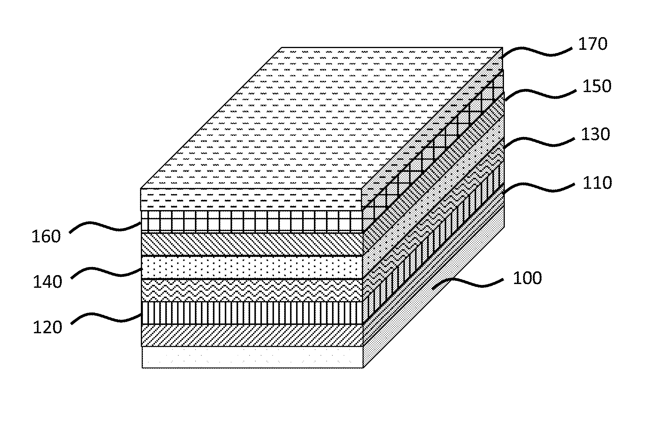
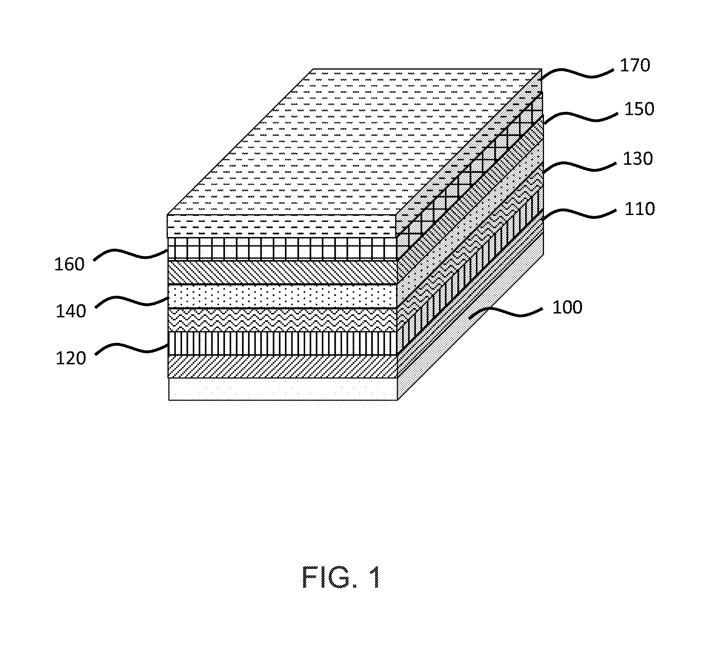
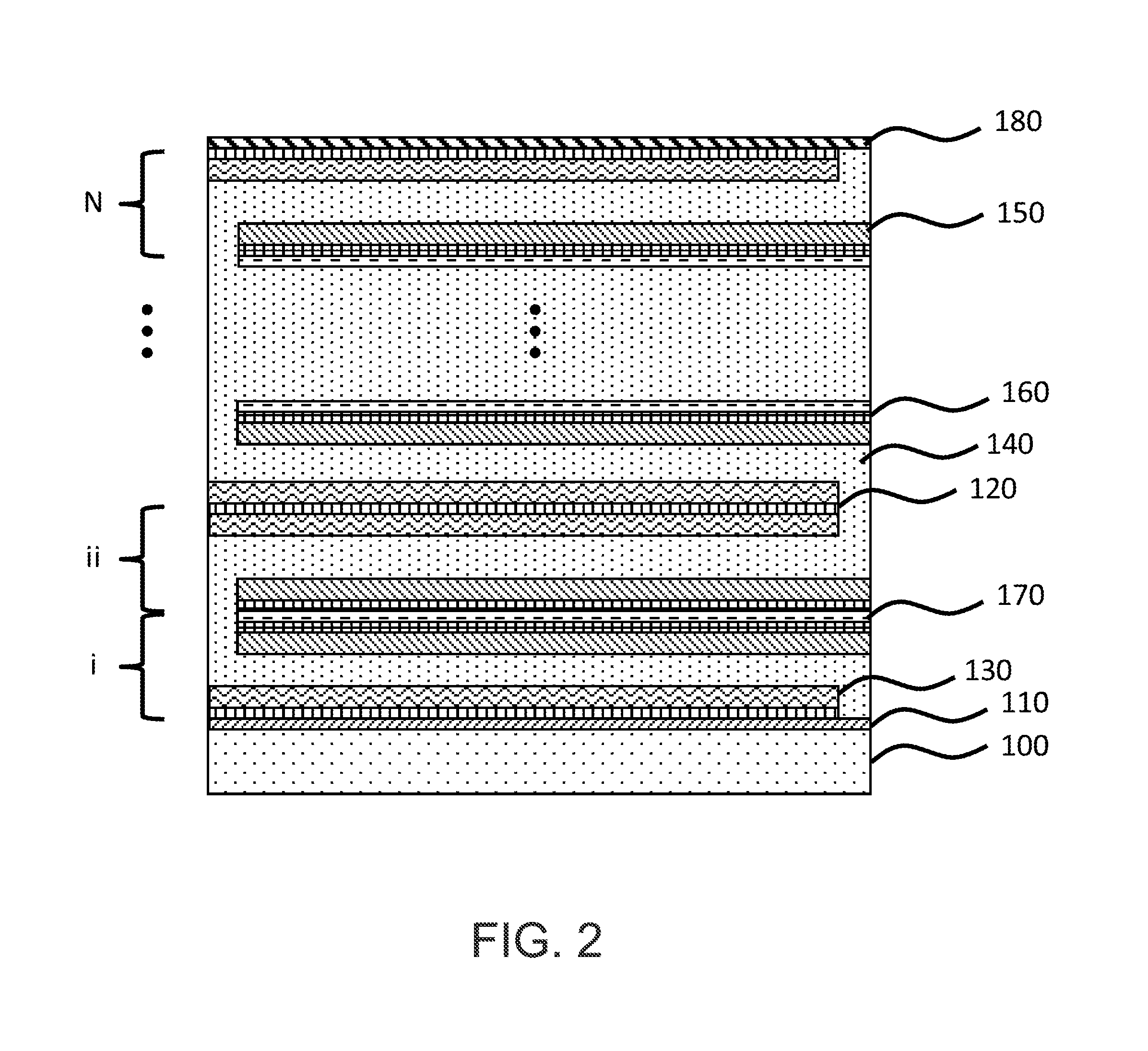
[0024]According to the present invention, techniques related to the manufacture of electrochemical cells are provided. More particularly, the present invention provides a method and device for fabricating a solid state thin film battery device using barrier regions. Merely by way of example, the invention has been provided with use of lithium based cells, but it would be recognized that other materials such as zinc, silver, copper and nickel could be designed in the same or like fashion. Additionally, such batteries can be used for a variety of applications such as portable electronics (cell phones, personal digital assistants, music players, video cameras, and the like), power tools, power supplies for military use (communications, lighting, imaging and the like), power supplies for aerospace applications (power for satellites), and power supplies for vehicle applications (hybrid electric vehicles, plug-in hybrid electric vehicles, and fully electric vehicles). The design of such b...


PUM

PropertyMeasurementUnit
Thicknessaaaaaaaaaa
Thicknessaaaaaaaaaa
Thicknessaaaaaaaaaa

Abstract

A thin film solid state battery configured with barrier regions formed on a flexible substrate member and method. The method includes forming a bottom thin film barrier material overlying and directly contacting a surface region of a substrate. A first current collector region can be formed overlying the bottom barrier material and forming a first cathode material overlying the first current collector region. A first electrolyte can be formed overlying the first cathode material, and a second current collector region can be formed overlying the first anode material. The method also includes forming an intermediary thin film barrier material overlying the second current collector region and forming a top thin film barrier material overlying the second electrochemical cell. The solid state battery can comprise the elements described in the method of fabrication.

Description

BACKGROUND OF THE INVENTION[0001]This present invention relates to manufacture of electrochemical cells. More particularly, the present invention provides a method and device for fabricating a solid state thin film battery device. Merely by way of example, the invention has been provided with use of lithium based cells, but it would be recognized that other materials such as zinc, silver, copper and nickel could be designed in the same or like fashion. Additionally, such batteries can be used for a variety of applications such as portable electronics (cell phones, personal digital assistants, music players, video cameras, and the like), power tools, power supplies for military use (communications, lighting, imaging and the like), power supplies for aerospace applications (power for satellites), and power supplies for vehicle applications (hybrid electric vehicles, plug-in hybrid electric vehicles, and fully electric vehicles). The design of such batteries is also applicable to cases...

Claims


Application Information

Patent Timeline
IPC IPC(8): H01M10/056H01M10/04C23C14/34C23C16/48C23C16/448H01M6/46B05D5/12H01M50/11H01M50/121
CPCC23C14/562H01M6/40H01M10/0436H01M10/052H01M10/0585Y02T10/7011Y10T29/49108H01M2/0202H01M2/024H01M2/0277H01M2/0285H01M2/0287H01M2/1646Y02E60/122Y02P70/50Y02E60/10H01M50/121H01M50/11Y02T10/70H01M50/124H01M4/049H01M4/131H01M4/663H01M4/0459H01M4/0445H01M10/049H01M10/0525H01M4/525H01M4/483H01M10/0562H01M2300/0071H01M4/661
Inventor KIM, HYONCHEOLLANGLOIS, MARCCHUNG, MYOUNGDOSASTRY, ANN MARIECHEN, YEN-HUNGBUCKINGHAM, STEPHEN
Owner SAKTI3
Why Eureka
Try Eureka