Gas-free fluid chamber

a fluid chamber and gas-free technology, applied in the field of fluid chamber devices, can solve the problems of gas-bubbles such as air trapped in the fluid chamber, impede the performance of pcr reactions, and (online) detection of amplified nucleic acid molecules

Inactive Publication Date: 2012-02-16
BIOCARTIS NV
View PDF2 Cites 9 Cited by
  • Summary
  • Abstract
  • Description
  • Claims
  • Application Information

AI Technical Summary

Benefits of technology

[0011]It is one objective of the present invention to provide a fluid chamber which can be used in a microfluidic device and allows for gas-free filling.

Problems solved by technology

One problem currently encountered during PCR reactions and particularly during online detection of real time PCR is that gas-bubbles such as air are trapped in the fluid chamber.
In view of the dimensions of the fluid chamber, such trapped gas-bubbles may impede the performance of the PCR reactions as well as the (online) detection of the amplified nucleic acid molecules.

Method used


Image

  • Gas-free fluid chamber
  • Gas-free fluid chamber
  • Gas-free fluid chamber

Examples


Embodiment Construction

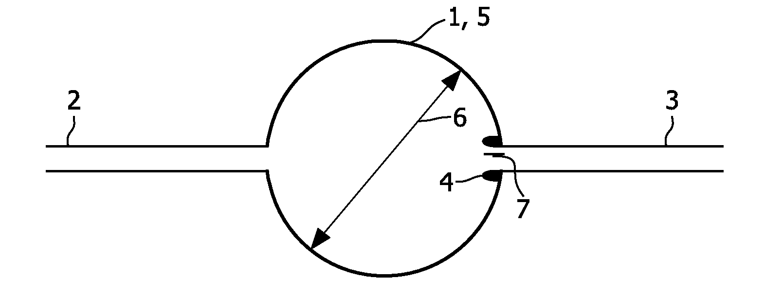
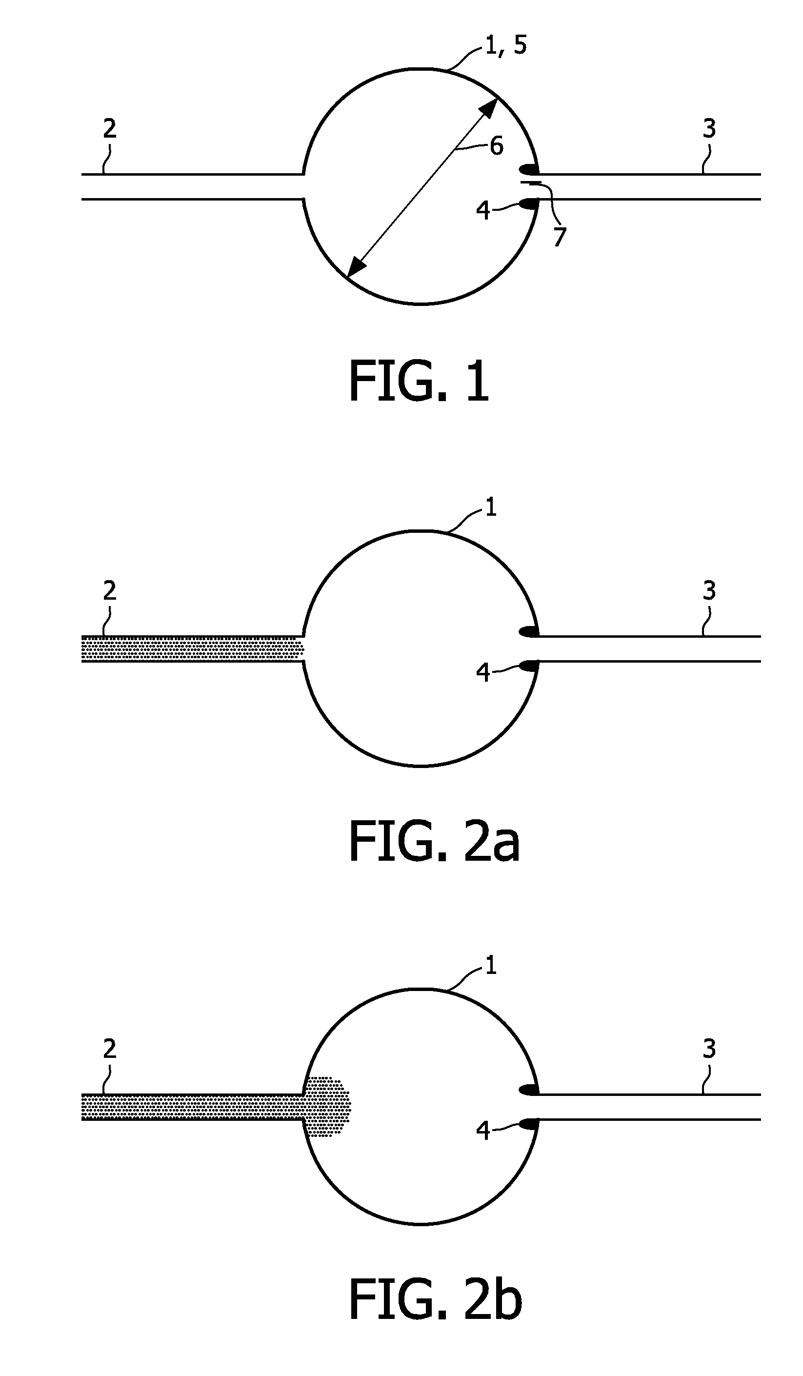
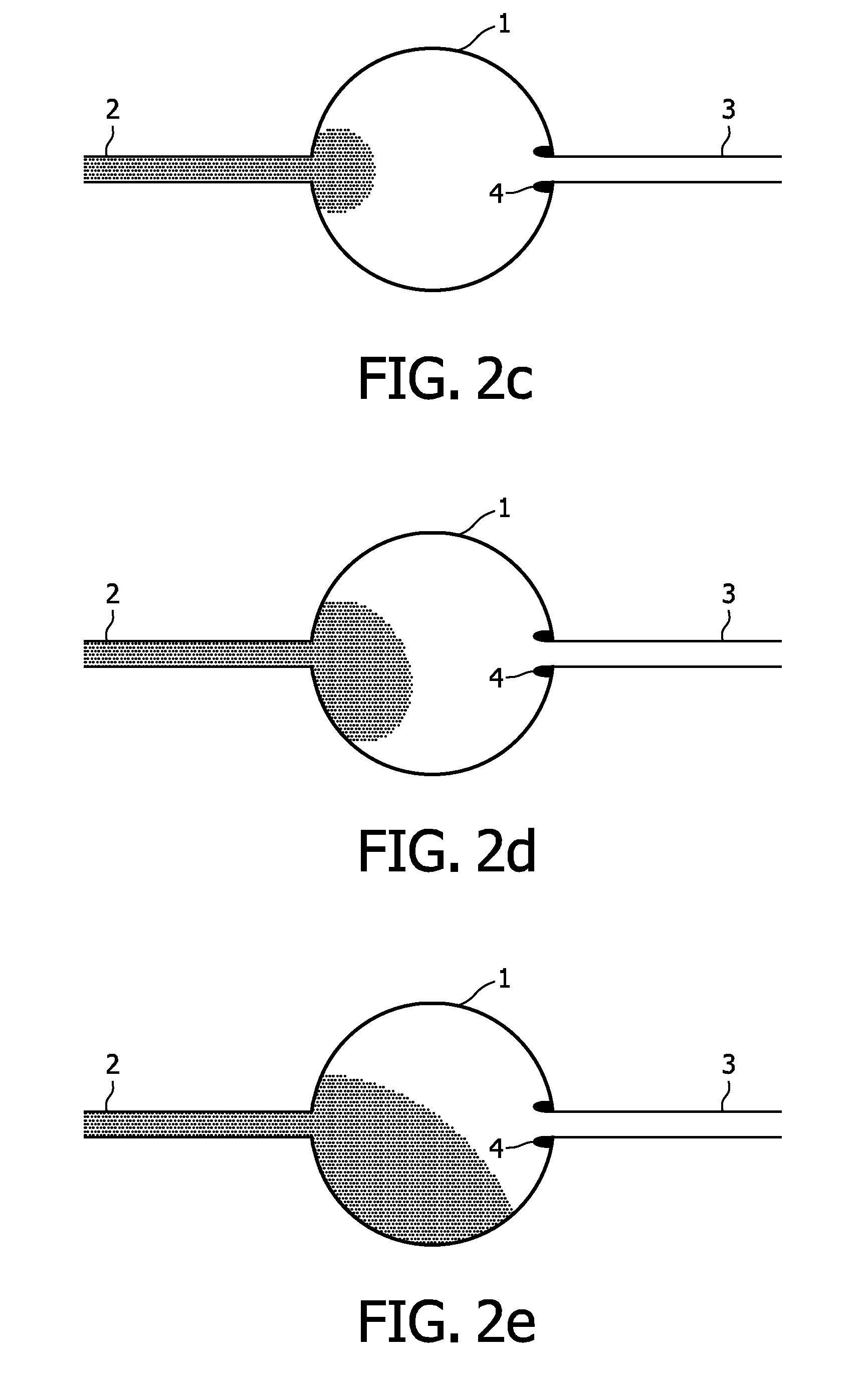
[0039]It has been found that positioning of a protrusion of circular or elliptical shape at the location where an outlet channel connects to a fluid chamber enables gas-free filling of a fluid chamber.

[0040]Before the invention is described in detail with respect to some of its preferred embodiments, the following general definitions are provided.

[0041]The present invention as illustratively described in the following may suitably be practiced in the absence of any element or elements, limitation or limitations, not specifically disclosed herein.

[0042]The present invention will be described with respect to particular embodiments and with reference to certain drawings but the invention is not limited thereto but only by the claims. The drawings as described are only schematic and non-limiting. In the drawings, the size of some of the elements may be exaggerated and not drawn on scale for illustrative purposes.

[0043]Where the term “comprising” is used in the present description and cl...


PUM

PropertyMeasurementUnit
heightaaaaaaaaaa
heightaaaaaaaaaa
diameteraaaaaaaaaa

Abstract

A Gas-free Fluid chamber for PCR. The present invention relates to a device with a fluid chamber suitable for performing a polymerized chain reaction for gas-free filling. Such devices may be used in the field of e.g. molecular diagnostics.

Description

FIELD OF THE INVENTION[0001]The present invention relates to a device with a fluid chamber suitable for, for instance, performing a polymerase chain reaction. Such devices may be used in the field of e.g. molecular diagnostics.BACKGROUND OF THE INVENTION[0002]In the field of molecular diagnostics, it is nowadays common to use microfluidic devices. Such microfluidic devices or microfluidic systems typically comprise a network of chambers which are connected by channels that provide for communication between the different fluid chambers. The fluid chambers as well as the channels typically have microscale dimensions with, for example, the dimensions of the channels typically being in the range of 0.1 μm to about 1 mm. Such microfluidic devices are described inter alia in U.S. Pat. No. 6,843,281 B1.[0003]A process that is commonly used in the field of molecular diagnostics is the so called polymerase chain reaction (PCR). During this reaction a small amount of liquid (typically 100 μl ...

Claims


Application Information

Patent Timeline
Patent Type & Authority Applications(United States)
IPC IPC(8): C12M1/34B65B3/04C12M1/00
CPCB01L3/502723B01L3/50851B01L7/52B01L2200/0605B01L2400/086B01L2200/0684B01L2300/0816B01L2300/18B01L2400/0406B01L2200/0642
Inventor BOUMA, PETER HERMANUSGEYSELAERS, MARTINUS LEONARDUS JOSEPHUS
Owner BIOCARTIS NV
Why Eureka
Try Eureka