Floating connector with flexible conductive member

a technology of flexible conductive parts and connectors, which is applied in the direction of connection insulation, electrical discharge lamps, coupling device connections, etc., can solve the problems of large space required for accommodating electric wires, difficult to form large-diameter electric wires inside restricted vehicle spaces, and difficulty in forming large-diameter electric wires. , to achieve the effect of saving accommodating space and decreasing connection reliability

Active Publication Date: 2012-02-16
YAZAKI CORP
View PDF4 Cites 59 Cited by
  • Summary
  • Abstract
  • Description
  • Claims
  • Application Information

AI Technical Summary

Benefits of technology

[0029]According to the present invention recited in claim 1, since the connector includes a outer housing attached to a case;
[0030]a first inner housing that accommodates a first terminal engaging with terminal in the mating connector and is movably accommodated within the outer housing along the engaging direction of the first terminal and the intersectional direction of the engaging direction, and engages with the mating connector; a second inner housing that accommodates a second terminal connected to an electric circuit in the case and is fixed within the outer housing; a connection portion that is made of flexible conductive member and electrically connects between the first terminal and the second terminal, the second terminal does not move even if the first inner housing and the first terminal move by engagement of the mating connector with the first inner housing, making it possible to prevent from producing stress in the electric circuit in the case electrically connected to the second terminal or decreasing the connection reliability between the second terminal and the electric circuit. Accordingly there is provided a connector that is able to absorb the misregistration with the mating connector and maintain connection condition to the electric circuit to be mounted in the case. Further, no need for electric wire to connect to the mating connector saves the accommodating space to accommodate the electric wire.
[0031]According to the present invention recited in claim 2, since the outer housing in the invention recited in claim 1 includes a first housing portion that is formed capable of the first inner housing and in the shape of tube with bottom and is provided with a through-bore through which the connection portion is passed through in the bottom wall, and further includes an elastic deformable packing that is attached to the first inner housing, integrally having a packing body in the shape of tube pressed fit between the outer circumference of the first inner housing and the inner circumference of the first housing and a annular cover positioned between the lower end surface of the first inner housing and the bottom wall of the first housing, there can be absorbed by the packing the misregistration between the mating connector and the first inner housing and the impact load applied to the first inner ho

Problems solved by technology

When the electric devices are connected each other by using large-diameter electric wire such as power source wire, however, it is difficult to form the large-diameter electric wire, and therefore more difficult to wire the large-diameter electric wire inside a restricted vehicle space.
In addition, because the large-diameter electric wire require large bend radius, a large space is required for accommodating the electric wire.
In this case, because receiving connectors of each electric device are directly conn

Method used


Image

  • Floating connector with flexible conductive member
  • Floating connector with flexible conductive member
  • Floating connector with flexible conductive member

Examples


Embodiment Construction

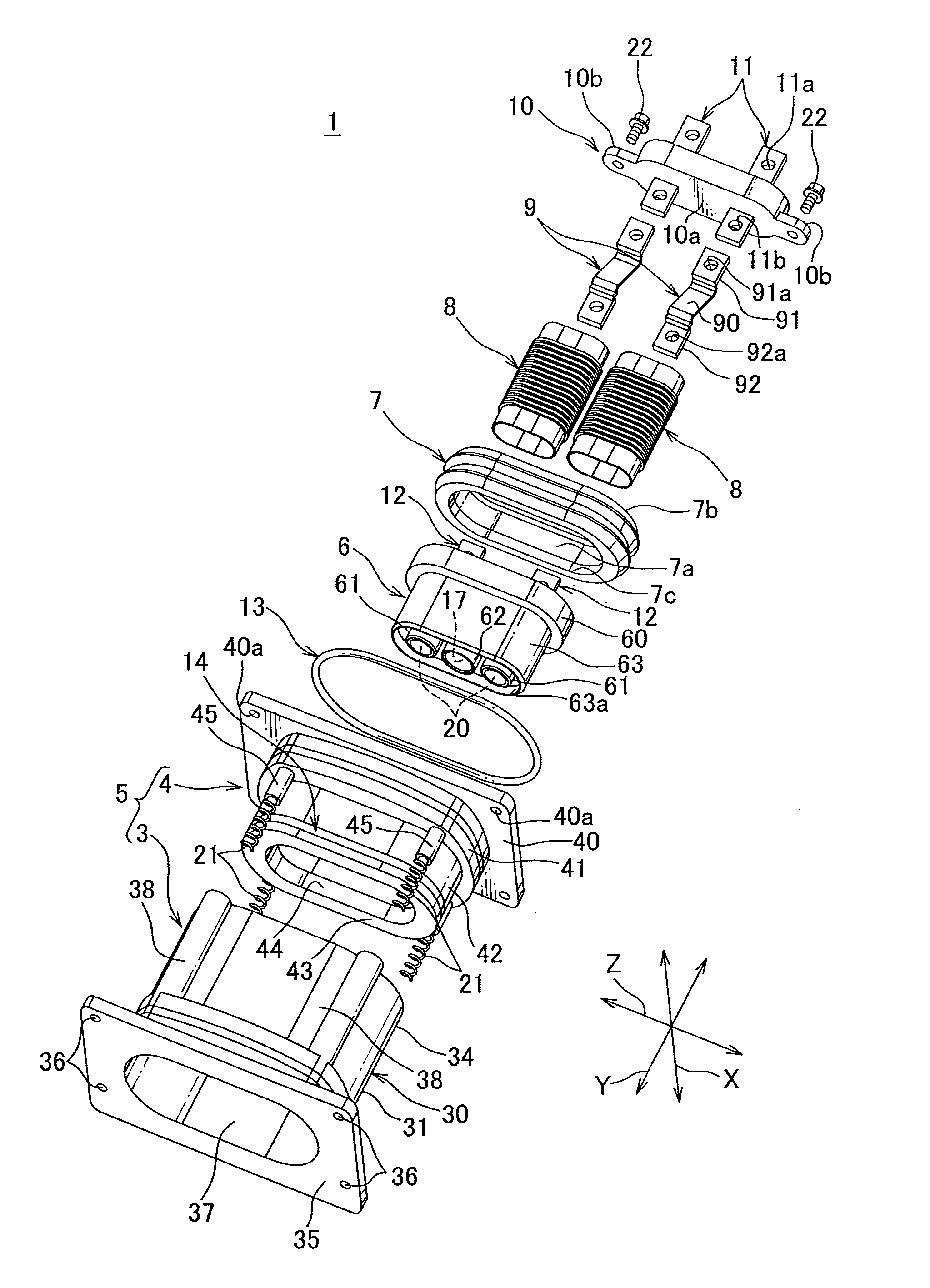
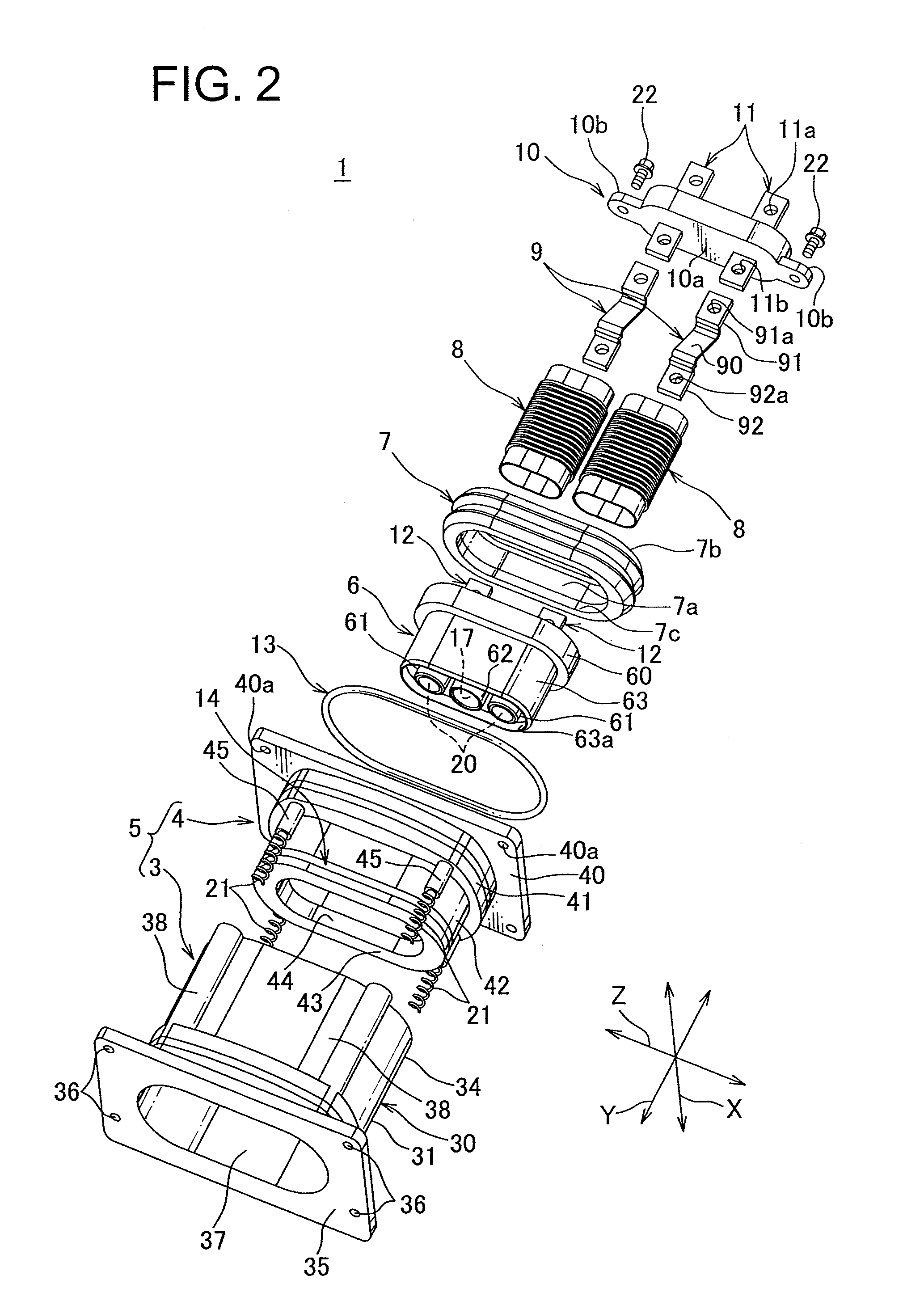
[0047]Hereafter, a connector according to a first embodiment in the invention is described with reference to FIGS. 1 to 11.

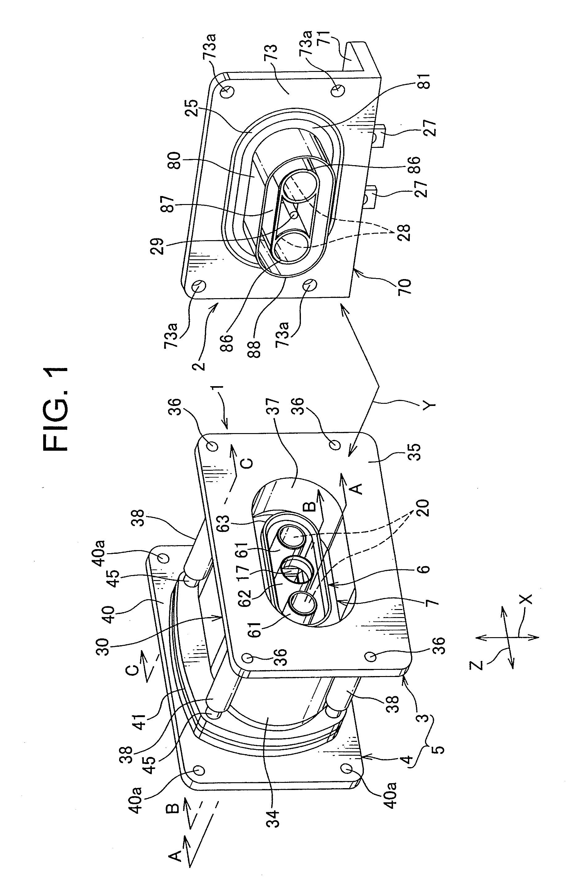
[0048]A connector 1 according to the invention is mounted in an inverter case attached to an automobile and is a receiving connector that is connected to a mating connector 2 attached to a motor case. In case that the inverter is mounted in the motor, the connector 1, i.e., is a receiving connector that is directly connected to the mating connector provided integrally with the motor.

[0049]An arrow Y shows a direction of an engagement between the mating connector and the connector 1, and a allow X shows a width direction of orthogonal oriented direction to the engaging direction and a allow Z shows a length direction of orthogonal oriented direction to the engaging direction.

[0050]The mating connector 2 mentioned above, as shown in FIGS. 1 and 6, includes a aluminum shield case 70 attached to the motor case, a synthetic-resin connector 80 mounted in the shield ca...


PUM


Abstract

There is provided a connector 1 connected to a mating connector, fixed in a case of a motor, comprising: an outer housing 5 attached to the case; a first inner housing 6 accommodating a first terminal 20 engaging to the mating connector, being accommodated in the outer housing 5 movably in the engaging direction Y of the first terminal 20 and in the intersectional direction of the engaging direction Y; a first inner connector 6 engaging to the mating connector; a second inner housing 10 accommodating a second terminal 11 electrically connected to a electric circuit in the case and being fixed in the outer housing 5 and a braided wire 90, and further including a connection portion 9 connecting the first terminal 20 and the second terminal 11 and a packing 7 attached to the first inner housing.

Description

BACKGROUND OF THE INVENTION[0001]1. Field of the Invention[0002]The present invention relates to a connector used for connecting electric devices to each other.[0003]2. Description of the Related Art[0004]Various electric devices are mounted in an automobile. A conventional wire harness has been used for connecting these electric devices to each other. The wire harness comprises a plurality of electric wire and a plurality of connectors attached to the ends of the electric wire. Each connection of the wire harness to a receiving connector fixed to a case of each electric device allows the electric devices to connect to each other. Note that the receiving connector is referred to as a connector fixed to a panel or a case.[0005]When the electric devices are connected each other by using large-diameter electric wire such as power source wire, however, it is difficult to form the large-diameter electric wire, and therefore more difficult to wire the large-diameter electric wire inside a...

Claims


Application Information

Patent Timeline
IPC IPC(8): H01R13/621H01R24/20
CPCH01R4/70H01R13/502H01R2201/26H01R13/6315H01R13/5219
Inventor TASHIRO, HARUNORI
Owner YAZAKI CORP
Why Eureka
Try Eureka