Interlock mechanism for a drug delivery device and drug delivery device

a technology of interlocking mechanism and drug delivery device, which is applied in the direction of medical syringes, intravenous devices, automatic syringes, etc., can solve the problems of affecting the safety of users, the device is more complicated to use, and the action required, for example pulling, pushing or twisting to charge the spring, etc. problem, to achieve the effect of preventing the device from being used, the main user risks have been identified with the devi

Active Publication Date: 2012-02-16
SANOFI AVENTIS DEUT GMBH
View PDF3 Cites 54 Cited by
  • Summary
  • Abstract
  • Description
  • Claims
  • Application Information

AI Technical Summary

Benefits of technology

[0016]a latch arm engageable with the catch for preventing rotation of the rotatable component;
[0021]translatively moving the trigger arm engaged with the protrusion of the latch arm from an initial position for pivoting the latch arm out of one of at least one catches provided in the cam profile of the rotatable component thus allowing the rotatable component, biased by an energy source to rotate;
[0024]The interlock means according to the invention allows for restricting the rotational movement of the rotatable component until the latch arm re-engages with the catch. This happens after one full rotation when only one catch is provided in the cam profile or after a fraction of a full rotation when more than one catch is provided. Another rotation cannot be triggered unless the interlocking means releases the trigger arm. This can be performed by some kind of user action to ensure that the triggering is intentional. The interlock means may be applied for ensuring that only one dose of the drug is delivered at a time in a multi-dose drug delivery device with each full or partial rotation of the rotatable component. Thus a user is prevented from administering multiple doses, e.g. by pressing a trigger button more than once or by holding the trigger button pressed whilst a needle is inserted into his body. Before a second injection can be triggered the user must perform some action that preferably cannot take place without first removing the needle from the body. Therefore, it is highly unlikely that the user could accidentally reset the interlock mechanism whilst the needle is inserted into the body.
[0029]In another embodiment the reset means may be operated when the safety cap is removed from the drug delivery device. This is particularly useful when the interlock mechanism is used for preventing accidental triggering of the drug delivery device, e.g. when carrying the device around in a bag.

Problems solved by technology

This may make the device more complicated to use, as it increases the number of user steps.
Also, the actions required, for example pulling, pushing or twisting to charge a spring, may be difficult for a user to perform, particularly if the user is elderly or has dexterity problems.
However, two main user risks have been identified with such a device.
Firstly, the user might press a trigger button several times or hold on to the trigger button for too long, causing multiple doses to be injected.
Secondly, there would be a risk of the device being triggered accidentally.
A dose setting knob is coupled to the spring and rotatably coupled to a housing such that rotation of the knob in a first direction results in compression or twisting of the spring.

Method used


Image

  • Interlock mechanism for a drug delivery device and drug delivery device
  • Interlock mechanism for a drug delivery device and drug delivery device
  • Interlock mechanism for a drug delivery device and drug delivery device

Examples


Embodiment Construction

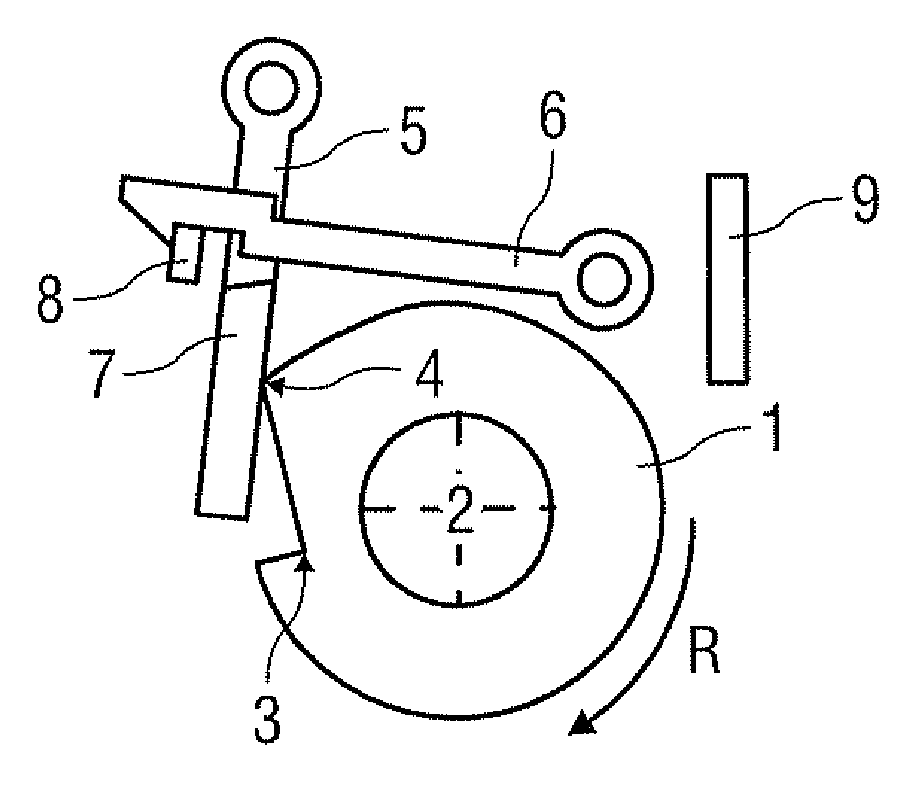
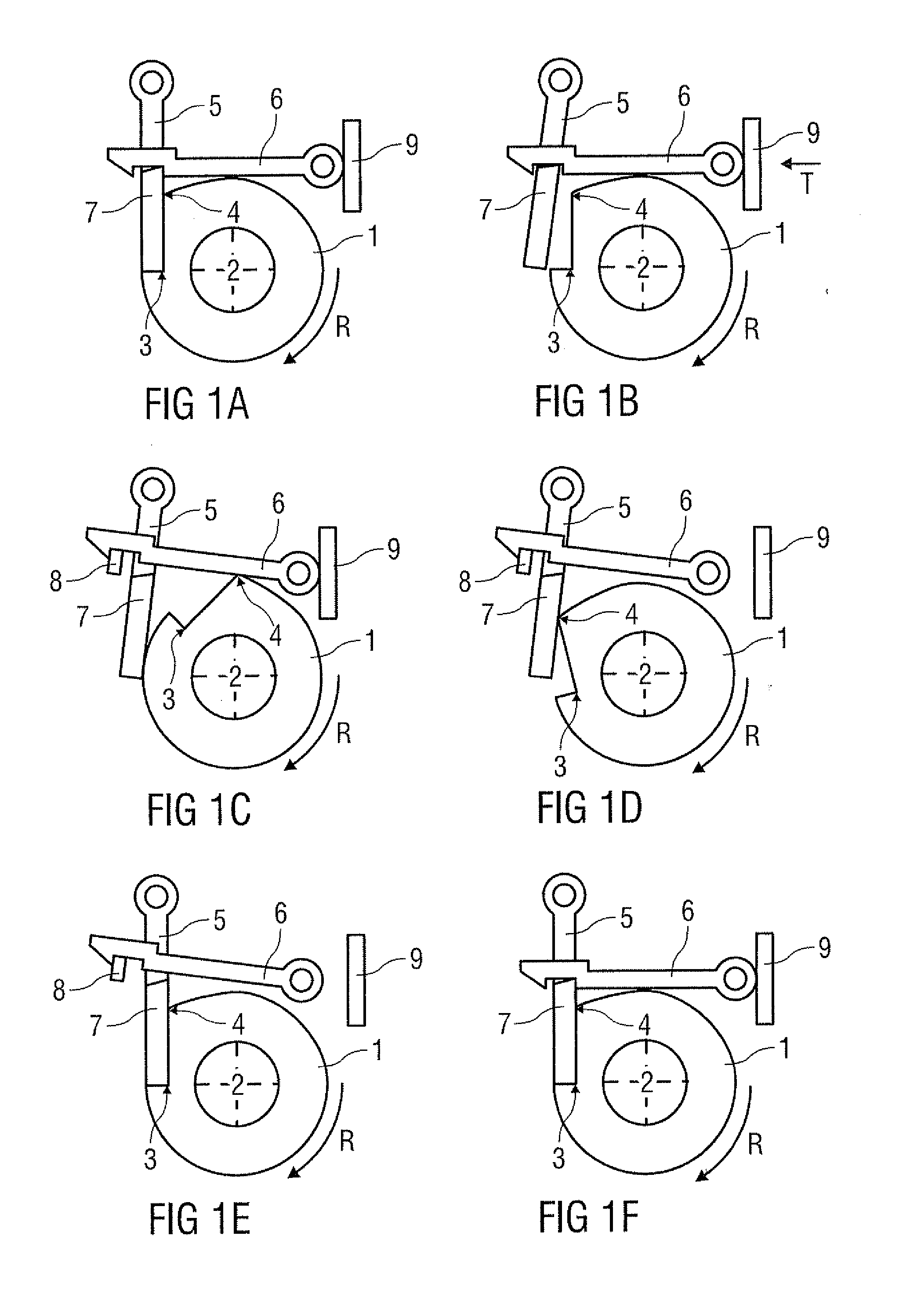
[0039]FIG. 1A shows a rotatable component 1 of a drug delivery device (not shown) with an interlock mechanism for controlling rotation R of the rotatable component 1. The embodiment shown is intended to be applied as a multiple-dose interlock mechanism that is suitable for a “screw” based autoinjector.

[0040]For the purposes of this description a “screw” based autoinjector mechanism is one where rotation of the rotatable component 1 about a longitudinal axis 2 (normal to the image plane of the figures) of the drug delivery device (autoinjector) causes a plunger / piston (not shown) to advance along a drug container body (syringe, not shown), forcing drug to be dispensed from the other end of the container (e.g. via a needle).

[0041]In this embodiment one dose of drug is delivered by one full rotation of the rotatable component 1.

[0042]The interlock mechanism comprises:

[0043]a cam profile on the rotatable component 1, the cam profile having a catch 3 and a cam 4;

[0044]a swivel mounted la...


PUM


Abstract

The invention refers to an interlock mechanism for restricting a rotational movement of a rotatable component (1) of a drug delivery device (10) and to a method for controlling the rotational movement of the rotatable component (1). The method comprises the steps of:translatively moving a trigger arm (6) engaged with a protrusion (7) of a latch arm (5) from an initial position for pivoting the latch arm (5) out of one of at least one catches (3) provided in a cam profile of the rotatable component (1) thus allowing the rotatable component (1), biased by an energy source, to rotate;pivoting the trigger arm (5) by one of at least one cams (4) provided in the cam profile during the rotation (R) of the rotatable component (1) whereby the trigger arm (6) is disengaged from the protrusion (7) thus allowing the latch arm (5) to re-engage with one of the catches (3) to stop the rotational movement (R) and whereby an interlock means (8) catches and holds the trigger arm (6) in its translatively moved and pivoted position until the interlock means (8) is released by a reset means;translatively moving the trigger arm (6) back into the initial position once the interlock means (8) is released thereby allowing it to pivot back and re-engage with the protrusion (7).

Description

CROSS REFERENCE TO RELATED APPLICATIONS[0001]The present application is a U.S. National Phase Application pursuant to 35 U.S.C. §371 of International Application No. PCT / EP2009 / 067388 filed Dec. 17, 2009, which claims priority to EP Patent Application No. 08022179.9 filed on Dec. 19, 2008. The entire disclosure contents of these applications are herewith incorporated by reference into the present application.FIELD OF THE INVENTION[0002]The invention refers to an interlock mechanism for restricting a rotational movement of a rotatable component of a drug delivery device. The invention also refers to a drug delivery device provided with such an interlock means. Furthermore, the invention refers to a method for controlling the rotational movement of the rotatable component of the drug delivery device by the interlock mechanism.BACKGROUND[0003]Autoinjector devices aim to make self-administration of injected therapies easier for patients. Current therapies delivered by means of self-admi...

Claims


Application Information

Patent Timeline
Patent Type & Authority Applications(United States)
IPC IPC(8): A61M5/31A61M5/30A61M5/20
CPCA61M5/31591A61M5/20
Inventor SMITH, CHRISOPHER JAMES
Owner SANOFI AVENTIS DEUT GMBH
Why Eureka
Try Eureka