Flow control and improved heat rise control device for water heaters

a technology for water heaters and flow control, which is applied in the field of water heaters, can solve the problems of reducing heating efficiency, unable to absorb heat, and prone to erosion, and reducing the efficiency of heat exchangers

Active Publication Date: 2012-02-23
ZODIAC POOL SYST LLC
View PDF4 Cites 14 Cited by
  • Summary
  • Abstract
  • Description
  • Claims
  • Application Information

AI Technical Summary

Problems solved by technology

1. Pool water is cool relative to the dew point of gas combustion products, making it possible to condense water vapor from those products. Unless the heater is designed to accommodate such condensation, corrosion or fouling of the heat exchanger can result. In heaters not designed for such condensation, it has been avoided by limiting the velocity of water flowing through the tubes.
2. Pool water often has high levels of dissolved solids, not only because of what may naturally occur in the water supply, but also because as water evaporates from the surface of the pool, the dissolved solids are left behind, increasing the concentration. In water heating appliances, dissolved solids tend to precipitate on the hot surfaces of heat exchangers, a phenomenon typically referred to as “liming.” The result of this precipitation is reduced heating efficiency and eventual failure of the heat exchanger. Liming can be avoided to a great extent by moving water over the heat exchanger surface at substantial velocity. In a pool heater this establishes a minimum velocity for water flow through the tubes. The required velocity depends on water temperature, however. If water is cool, lower velocities can be tolerated without liming, and conversely, higher velocities may be necessary if water is hot.
3. Flow of water in a tube can cause “erosion,” a phenomenon in which metal is removed from the tube surface by combined mechanical and chemical action. Copper, which is commonly used in swimming pool heat exchangers, is especially vulnerable to erosion. The extent of erosion depends on the water chemistry and the velocity of water flow in the tube. In the design of a pool heater the effect is to limit the velocity of water flow.
4. If water velocity is too low, the water may not be able to absorb heat at the rate the heat is delivered by the heat exchanger surface. In that case, “steam flashing” (boiling) occurs at the surface and heat transfer becomes even worse, resulting in destruction of the exchanger.
5. Some pool heaters are designed for very high heating efficiency, and in those heaters, condensation of combustion product water is intended. Extraction of heat is maximized by cooling the products to temperatures below their dew point, thereby recapturing the heat of vaporization. Heat exchanger surfaces must be as cool as possible to accomplish condensation. Several factors affect the temperature of heat exchanger surfaces, but a major factor is water velocity. High velocity cools exchanger surfaces. (Heat exchangers in high efficiency heaters typically operate with condensation only in a specific section of the exchanger and have means for handling and disposal of condensed water in that section. Water flow requirements in the condensing and non-condensing sections differ.)
6. Modern swimming pool systems often include pumping and control equipment capable of circulating pool water at differing flow rates in order to accomplish filtration and heating with minimum use of electrical energy. A common approach is to operate the circulating pump at half of normal speed when possible. On a given system, pump power changes with the cube of pump speed, so resulting energy savings are substantial. In such systems, pool heaters must be capable of operating reliably and efficiently regardless of the system flow rate.
7. At any water flow rate, heating efficiency can be increased by reducing the gas energy input. Doing so effectively increases the amount of heat transfer surface per unit of energy input. In heaters capable of operating at reduced input, control design must be done in consideration of the water flow rate.
In view of these numerous and counter-acting factors, design of a pool heater heat exchanger is a complicated process.
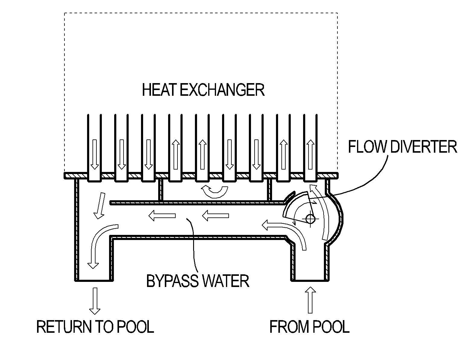
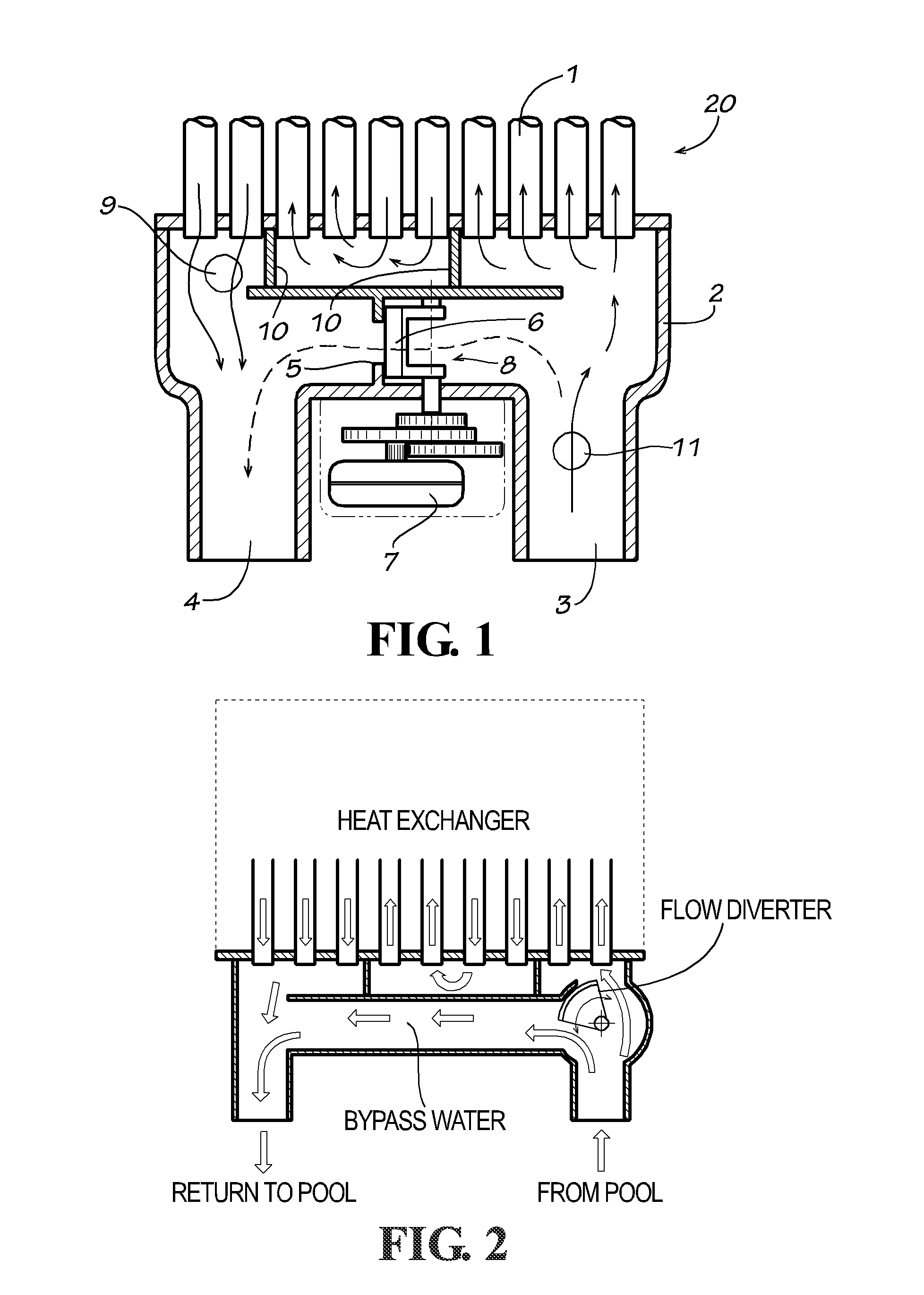
In addition to providing suitable flow through the exchanger, by-pass of water reduces pressure drop through the heater, and thereby reduces pumping power.
Both the spring-loaded by-pass valve method and the thermostatic valve method have limitations on the degree of control they provide, and are also limited by a minimum flow rate at which the heater will operate.

Method used


Image

  • Flow control and improved heat rise control device for water heaters
  • Flow control and improved heat rise control device for water heaters

Examples


Embodiment Construction

[0022]Embodiments of the invention provide a means to control the flow of water to a heater and the resulting water temperature rise to allow a heater to operate under greatly varying flow and inlet water temperature conditions. Specifically, embodiments of the invention utilize a valve mechanism, such as a diverter or other suitable device, that controls the amount of water passing through the heater tubes or coils of the heat exchanger and the amount of water that by-passes the heater without passing through the heater tubes or coils of the heat exchanger. Controlling the amount of water passing through the heater tubes or coils may be accomplished by controlling the water flow through the by-pass area, by controlling the opening entering the heater tubes or coils, or a combination of both. FIG. 1 illustrates the control of water flow through the by-pass area alone by way of diverter 6. FIG. 2 illustrates a similar design that affords even more control, as the diverter is position...


PUM


Abstract

Disclosed are systems and devices for controlling the amount of water passing through a heat exchanger and the amount of water that by-passes the heater without passing through the heat exchanger. In some embodiments, the system includes a by-pass valve assembly having means for sensing a time-varying characteristic of fluid adjacent the inlet, means for sensing a time-varying characteristic of fluid adjacent the outlet, and a valve that alters the amount of fluid by-passing the fluid heater in response to differences in the time-varying characteristic of fluid adjacent the inlet and fluid adjacent the outlet.

Description

RELATED APPLICATIONS[0001]This application claims the benefit of U.S. Provisional Application Ser. No. 61 / 374,661 filed Aug. 18, 2010 titled “Improved Flow Control and Improved Heat Rise Control Device for Water Heaters,” the content of which is hereby incorporated by reference.FIELD OF THE INVENTION[0002]This invention relates to water heaters, more specifically, but not exclusively to, gas-fired swimming pool heaters.BACKGROUND[0003]Experience with gas-fired swimming pool heaters over a period of several decades has resulted in designs that accommodate the unique technical challenges involved in heating pool water. In most heaters of current design, water is passed through finned tubing through which heat from gas combustion is transferred to it. It is necessary to control the water flow rate through the heat exchanger tubes for several reasons:[0004]1. Pool water is cool relative to the dew point of gas combustion products, making it possible to condense water vapor from those pr...

Claims


Application Information

Patent Timeline
Patent Type & Authority Applications(United States)
IPC IPC(8): F24H9/20E04H4/14F24H1/14
CPCF24H9/2035F24H9/0015F24H1/0081F24H1/40E04H4/129F24H1/54F24H15/36F24H15/219F24H15/156F24H15/325F24H15/215
Inventor MC QUEEN, E. KEITHCOLOMES, EMILY R.MASKELL, BRUCE WILLIAM
Owner ZODIAC POOL SYST LLC
Why Eureka
Try Eureka