
Integrated photovoltaic module

a photovoltaic module and integrated technology, applied in the direction of electric variable regulation, process and machine control, instruments, etc., can solve the problems of insufficient solution of mic approaches such as those illustrated in figs. 3 and 4, and inability to fully solve complete strings, etc., to achieve the effect of simplifying wiring

Inactive Publication Date: 2012-02-23
UNIV OF COLORADO THE REGENTS OF
View PDF6 Cites 106 Cited by
  • Summary
  • Abstract
  • Description
  • Claims
  • Application Information

AI Technical Summary

Benefits of technology

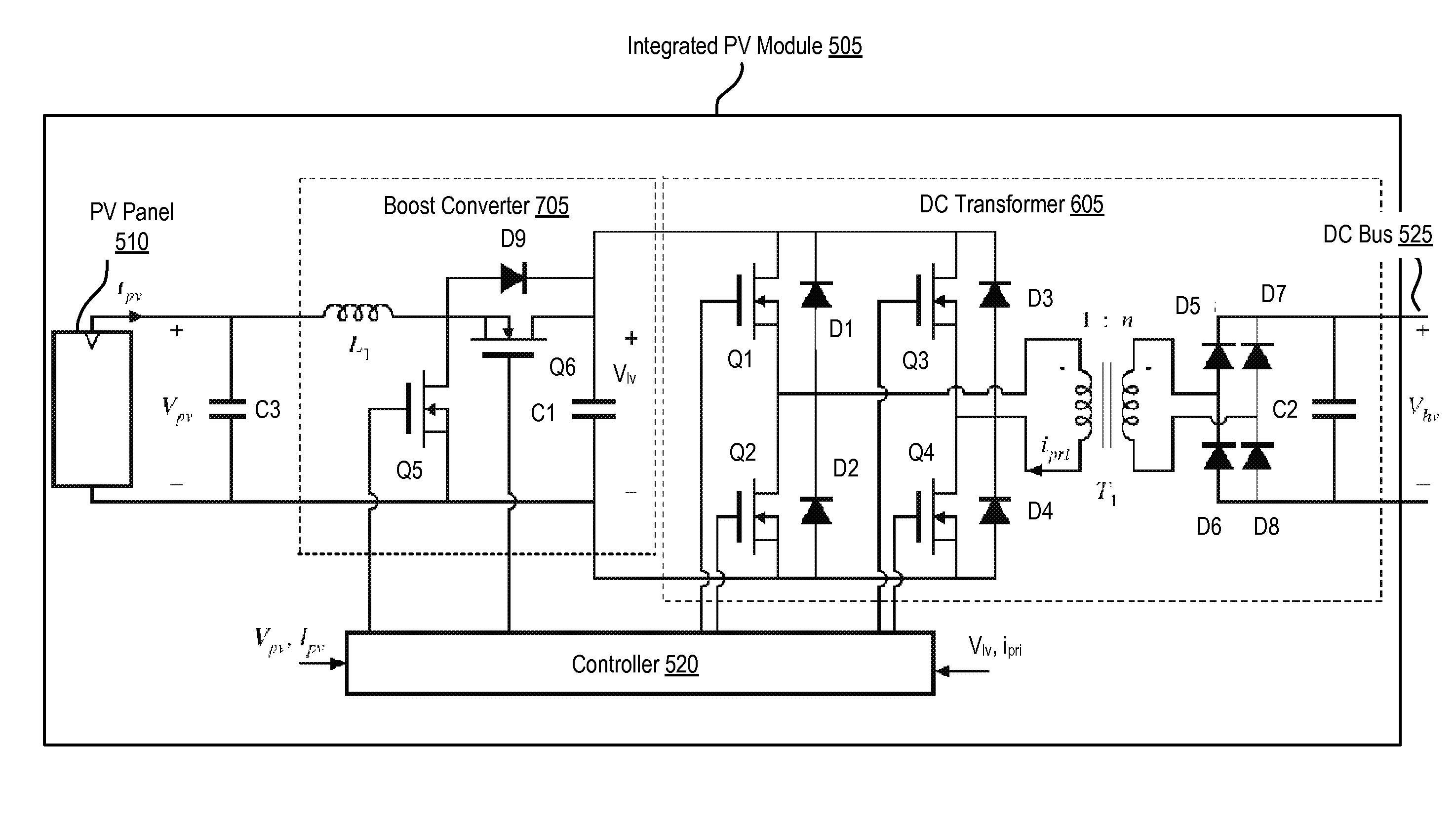
[0015]In one embodiment, the outputs of multiple integrated PV modules are connected in parallel to a high-voltage bus, simplifying the wiring between integrated PV modules. A central inverter coupled to the high-voltage bus provides a grid interface between the multiple integrated PV modules and an ac utility. For example, one benefit of the resulting integrated PV modules is that they can be configured to provide maximum power point tracking on a fine scale. The integrated PV modules may be included in a building-integrated PV element such as a PV roof shingle.

Problems solved by technology

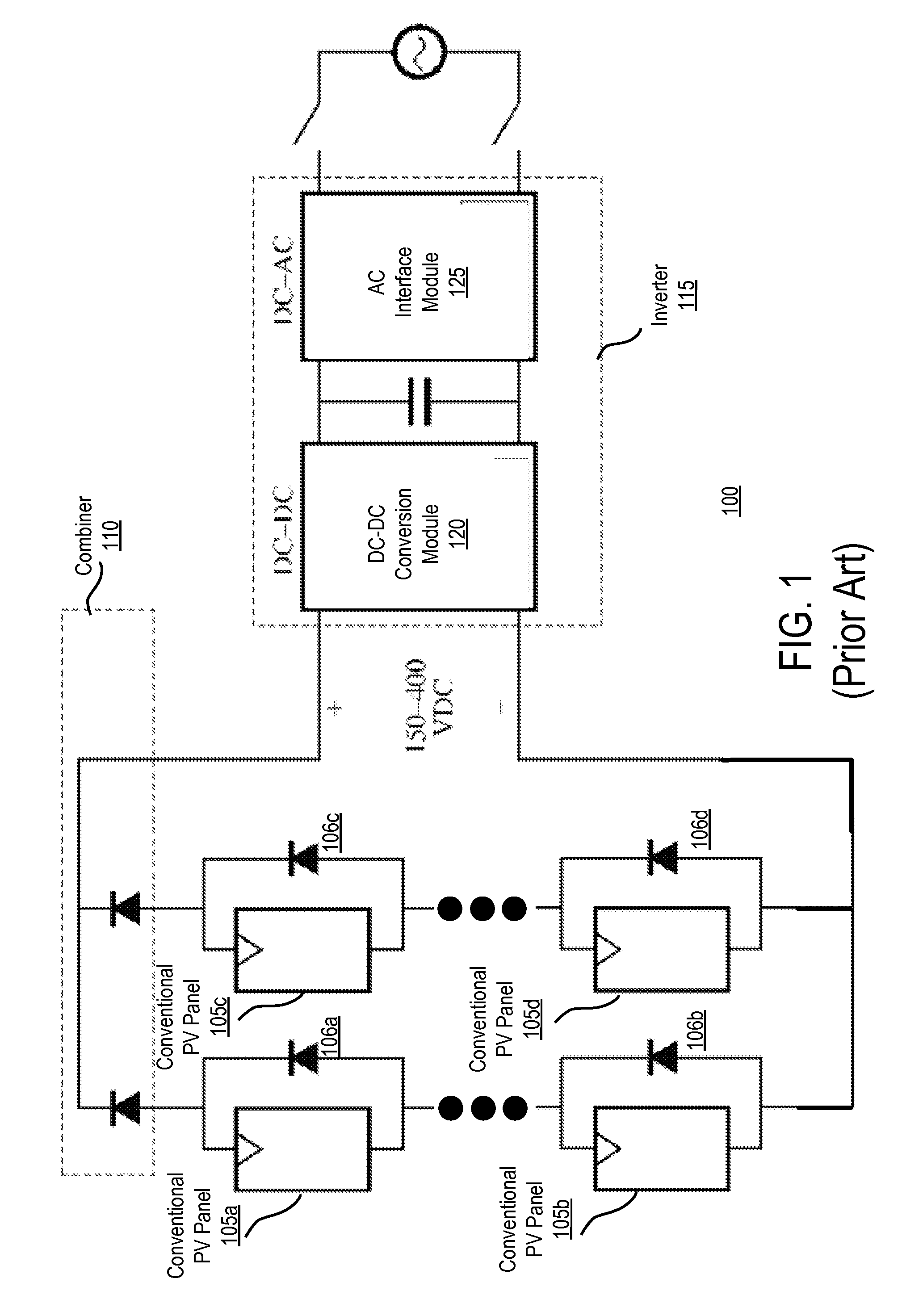
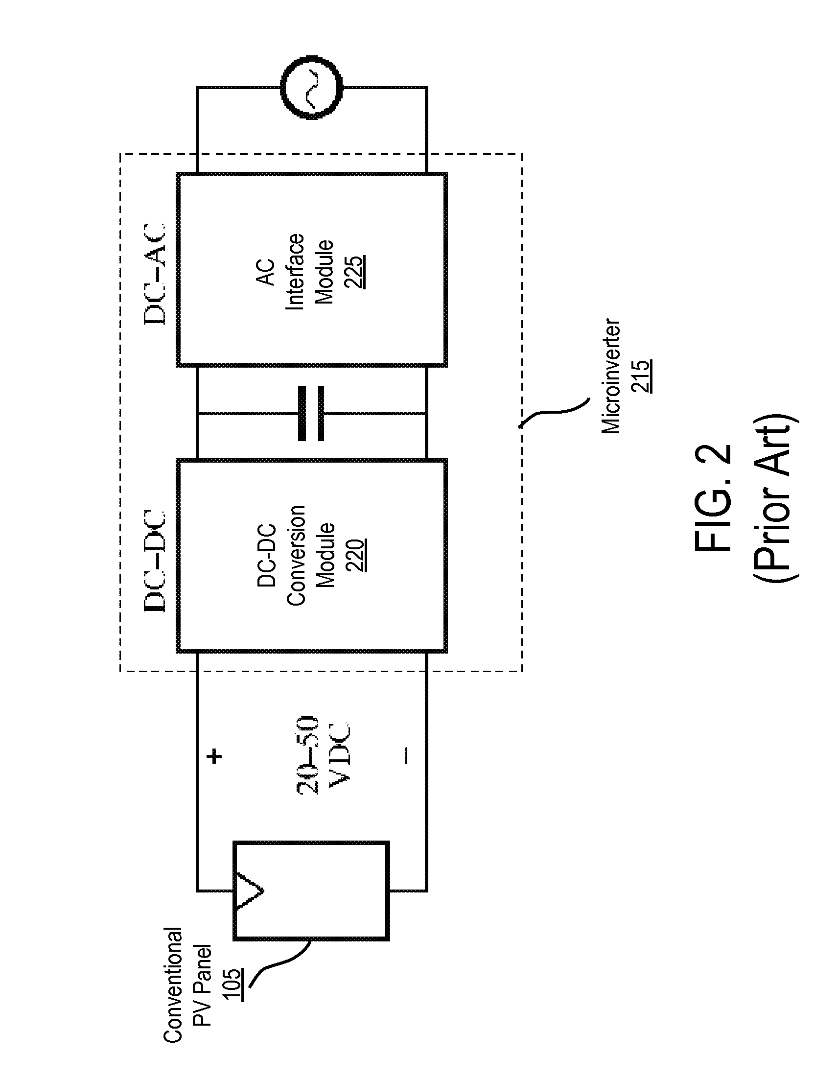
As a result, the per-panel microinverter 215 approach can be prohibitively expensive and unreliable.
However, MIC approaches such as those illustrated in FIGS. 3 and 4 are not fully adequate solutions.
They require more complex wiring of both series and parallel strings of conventional PV panels, and a faulty connection in one coventional PV panel can still disrupt the operation of the other coventional PV panels in the string, potentially causing the complete string to fail (produce no current).

Method used


Image

  • Integrated photovoltaic module
  • Integrated photovoltaic module
  • Integrated photovoltaic module

Examples


Embodiment Construction

[0029]The Figures (FIGS.) and the following description relate to preferred embodiments by way of illustration only. It should be noted that from the following discussion, alternative embodiments of the structures and methods disclosed herein will be readily recognized as viable alternatives that may be employed without departing from the principles of what is claimed.

[0030]Reference will now be made in detail to several embodiments, examples of which are illustrated in the accompanying figures. It is noted that wherever practicable similar or like reference numbers may be used in the Figures and may indicate similar or like functionality. The Figures depict embodiments of the disclosed system (or method) for purposes of illustration only. One skilled in the art will readily recognize from the following description that alternative embodiments of the structures and methods illustrated herein may be employed without departing from the principles described herein.

[0031]General Overvie...


PUM


Abstract

The disclosed embodiments increase the power generated by a photovoltaic (PV) array, when the PV panels within the PV array are not uniformly illuminated or oriented or when PV panels are mismatched (e.g., have varying performance characteristics) and / or operate at non-uniform temperatures. It also provides simpler interconnection and wiring of the elements (e.g., PV panels) of the array. A dc-dc converter comprised of a DC transformer is coupled to each PV panel in a photovoltaic array to generate an increased dc voltage from a lower dc voltage produced by the PV panel. The outputs of the dc-dc converters are connected in parallel to a dc bus, which distributes the resulting voltage. As a result, the energy generated by the PV array is increased, the costs of system design and installation are reduced, and it becomes feasible to install PV arrays in new locations such as on gabled or non-planar roofs.

Description

BACKGROUND[0001]1. Field of Art[0002]This disclosure relates generally to the field of photovoltaic power systems. More specifically, this disclosure relates to integrated photovoltaic modules that include highly efficient dc-dc conversion circuitry that improves energy capture of a photovoltaic array.[0003]2. Description of the Related Art[0004]Solar photovoltaic (PV) cells typically produce dc voltages of less than one volt. The amount of electrical power produced by such a cell is equal to its dc voltage multiplied by its dc current, and these quantities depend on multiple factors including the solar irradiance, cell temperature, process variations and cell electrical operating point. It is commonly desired to produce more power than can be generated by a single cell, and hence multiple cells are employed. It is also commonly desired to supply power at voltages substantially higher than the voltage generated by a single cell. Hence, multiple cells are typically connected in serie...

Claims


Application Information

Patent Timeline
Patent Type & Authority Applications(United States)
IPC IPC(8): E04D13/18H02J1/00H02M3/335
CPCH01L31/02021H02J3/383Y02E10/563Y02B10/12Y02B10/14H02M3/285H02J2300/24H02J3/381Y02B10/10Y02E10/56H02J2300/26H02J3/46
Inventor ERICKSON, JR., ROBERT WARREN
Owner UNIV OF COLORADO THE REGENTS OF
Learn More