Swirler, combustion chamber, and gas turbine with improved mixing

a gas turbine and combustion chamber technology, applied in the field of swirlers, can solve the problems of affecting the mixing of fuel and air, affecting the mixing of air, and taking considerable effort to keep the pollutants as low as possible, so as to improve the mixing of air and promote the mixing of fuel and air

Inactive Publication Date: 2012-02-23
SIEMENS AG
View PDF3 Cites 18 Cited by
  • Summary
  • Abstract
  • Description
  • Claims
  • Application Information

AI Technical Summary

Benefits of technology

[0022]This may enable a maximum interaction with the air flow for vortex generation with the consequence that fuel and air mixing is promoted. Especially in locations close to the air inlet of the mixing channel, the flow direction of the air may not be totally parallel, so that a number of dimples may, for example, be arranged on a curved fictitious base line or the dimpl...

Problems solved by technology

However, burning the fuel leads to a number of undesired pollutants in the exhaust gas which can cause damage to the environment.
Therefore, it takes considerable effort to keep the pollutants as low as po...

Method used


Image

  • Swirler, combustion chamber, and gas turbine with improved mixing
  • Swirler, combustion chamber, and gas turbine with improved mixing
  • Swirler, combustion chamber, and gas turbine with improved mixing

Examples


Embodiment Construction

[0037]Not shown, a gas turbine engine comprises a compressor section, a combustor section and a turbine section which are arranged adjacent to each other. In operation of the gas turbine engine air is compressed by the compressor section and output to the burner section with one or more combustors.

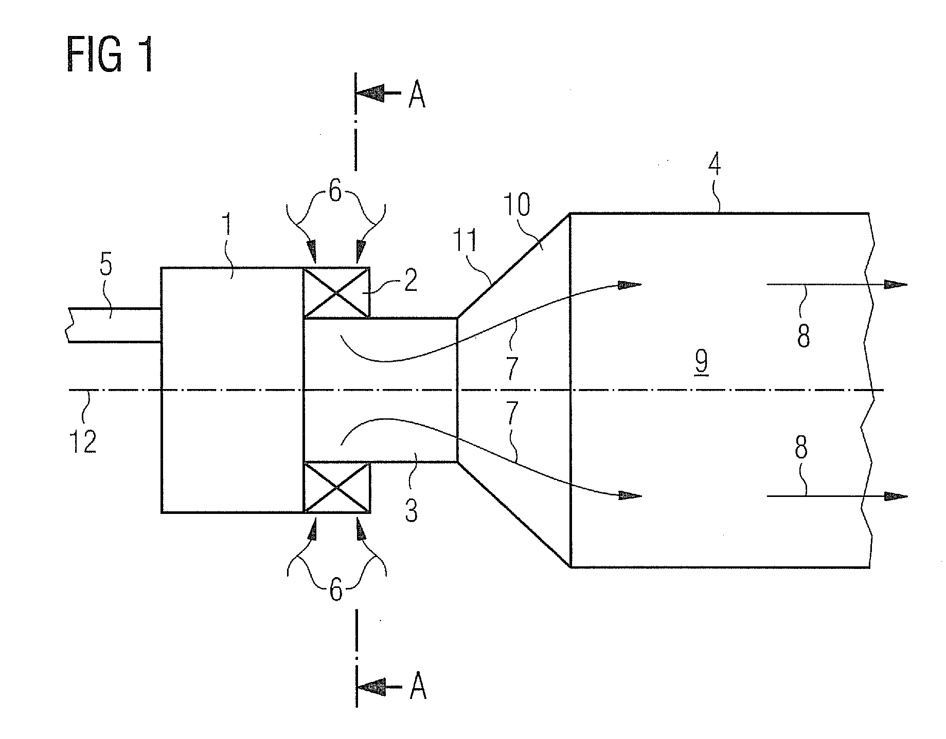
[0038]FIG. 1 shows a longitudinal section through a combustor, specifically a combustor within a gas turbine engine (not shown). The combustor comprises relative to a flow direction: a burner comprising a burner-head 1 and a radial-type swirler 2 attached to the burner-head 1, a transition piece referred to as combustion pre-chamber 3 and a main combustion chamber 4. The main combustion chamber 4 has a diameter being larger than the diameter of the pre-chamber 3. The main combustion chamber 4 is connected to the pre-chamber 3 via a dome portion 10 comprising a dome plate 11. In general, the transition piece 3 may be implemented as a one part continuation of the burner towards the combustio...


PUM


Abstract

A swirler for mixing fuel and air is provided. The swirler includes a plurality of vanes positioned radially around a central axis of the swirler and a plurality of mixing channels for mixing the fuel and the air. At least one mixing channel of the plurality of mixing channels is defined by opposite walls of two adjacent vanes of the plurality of vanes and is comprising at least one fuel injection opening and is further comprising at least one dimple for generating a vortex of the air. Further, a combustion chamber incorporating such a swirler and a gas turbine incorporating such a combustion chamber are provided.

Description

FIELD OF THE INVENTION[0001]The invention relates to a swirler, particularly of a gas turbine, and improvements for the further diminishment of air pollutants such as nitrogen oxides (NOX).BACKGROUND OF THE INVENTION[0002]In a gas turbine burner a fuel is burned to produce hot pressurised exhaust gases which are then fed to a turbine stage where they, while expanding and cooling, transfer momentum to turbine blades thereby imposing a rotational movement on a turbine rotor. Mechanical power of the turbine rotor can then be used to drive a generator for producing electrical power or to drive a machine. However, burning the fuel leads to a number of undesired pollutants in the exhaust gas which can cause damage to the environment. Therefore, it takes considerable effort to keep the pollutants as low as possible. One kind of pollutant is nitrogen oxide (NOX). The rate of formation of nitrogen oxide depends exponentially on the temperature of the combustion flame. It is therefore attempt...

Claims


Application Information

Patent Timeline
IPC IPC(8): F23R3/28
CPCF23C7/004F23R3/286F23R3/14
Inventor LAM, KAM-KEI
Owner SIEMENS AG
Why Eureka
Try Eureka