Method and apparatus for homogenizing a glass melt

a technology of glass melt and homogenizing glass, which is applied in the field of reducing contaminants in glass melt, can solve the problems of inclusion or blister defects in glass products, difficult to control the temperature of glass free surfaces, and stratification of condensation

Active Publication Date: 2012-02-23
CORNING INC
View PDF9 Cites 11 Cited by
  • Summary
  • Abstract
  • Description
  • Claims
  • Application Information

AI Technical Summary

Benefits of technology

[0013]The method may further comprise sensing a temperature within the annular gap 52 with a thermocouple 58 disposed within the stirring vessel cover 14. The sensed temperature can then be used to control the magnitude of an electrical current supplied to the heating element, thereby regulating a temperature of the aperture-defining surface and the annular gap 52 between the surface 40 and the stirrer shaft 24.
[0014]The invention will be understood more easily and other objects, characteristics, details and advantages thereof will become more clearly apparent in the course of the following explanatory description, which is given, without in any way implying a limitation, with reference to the attached Figures.

Problems solved by technology

When the resulting condensates reach a critical size they can break off, falling into the glass and causing inclusion or blister defects in the glass product.
Heating the shaft above the glass free surface has proven only partially successful in reducing particulate contamination in the glass melt, resulting only in a stratification of the condensation.
However, such methods may make it difficult to control the temperature of the glass free surface, such as by heating the chamber cover above the glass.
In addition, the joint between the shield and the stirrer shaft may serve as an additional source of condensate contamination.

Method used


Image

  • Method and apparatus for homogenizing a glass melt
  • Method and apparatus for homogenizing a glass melt
  • Method and apparatus for homogenizing a glass melt

Examples


Embodiment Construction

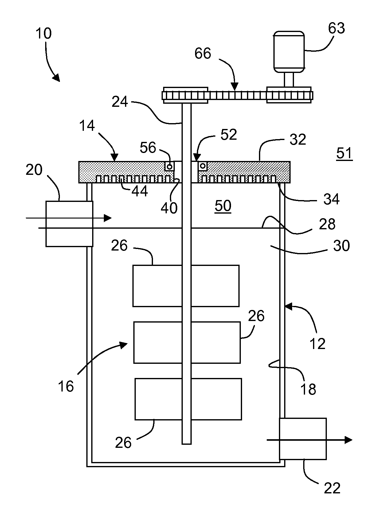
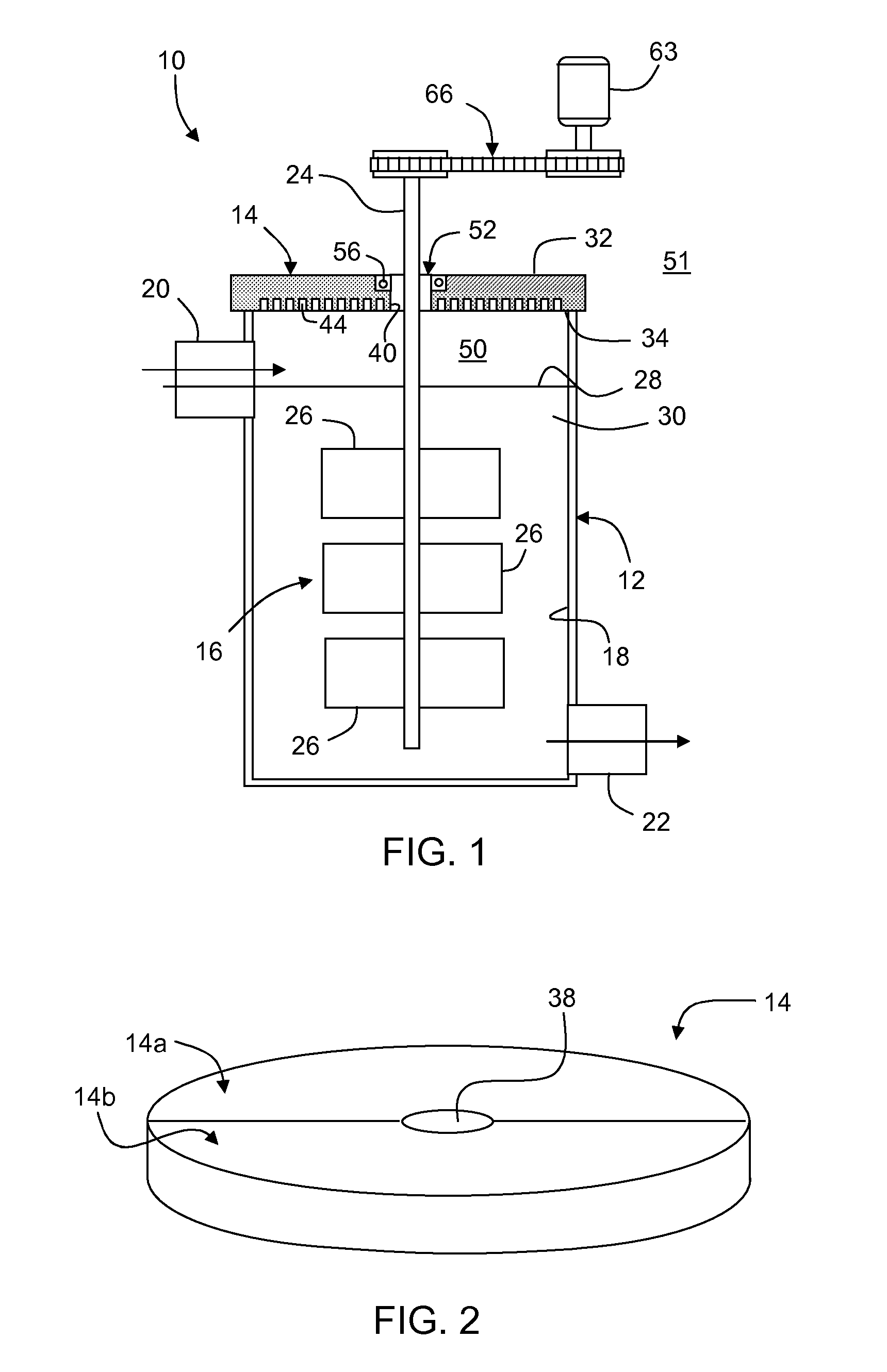
[0020]FIG. 1 illustrates an exemplary apparatus for practicing a method for homogenizing a glass melt according to an embodiment of the present invention. Stirring apparatus 10 of FIG. 1 includes stirring vessel 12, stirring vessel cover 14 and stirrer 16.

[0021]Stirring vessel 12 is preferably cylindrically-shaped and substantially vertically-oriented, although the stirring vessel may have other shapes and orientations as needed. Preferably, the stirring vessel includes inner surface 18 comprising platinum or a platinum alloy. Other materials having resistance to high temperature, including resistance to corrosion, as well as electrical conductivity, may be substituted. For example, suitable metals for forming inner surface 18 can include other platinum group metals such as rhodium, iridium, palladium, ruthenium, osmium and alloys thereof. Stirring vessel 12 comprises molten glass inlet pipe 20 located at or near the top of stirring vessel 12 and molten glass outlet pipe 22 located ...


PUM

PropertyMeasurementUnit
temperatureaaaaaaaaaa
Chemicalaaaaaaaaaa

Abstract

The present invention is directed toward a method of reducing contamination of a glass melt in a stirring apparatus by an oxide material. The oxide material, such as platinum oxide, may be volatilized by the high temperature of the glass melt, and then condense on the inside surfaces of a stirring vessel, particularly the stirrer shaft and surrounding surfaces of the stirring vessel cover. A build-up of condensed oxide material may then be dislodged and fall back into the glass melt. Accordingly, an apparatus and method is provided that includes a heating element disposed adjacent an annular gap between the stirring vessel cover and the stirrer shaft. The heating element heats a surface of the stirring vessel cover bounding the annular gap and prevents condensation of volatile oxides that may flow through the annular gap.

Description

BACKGROUND OF THE INVENTION[0001]1. Field of the Invention[0002]The invention relates generally to a method of reducing contaminants in a glass melt, and more specifically to reducing condensation-formed contaminants during a glass stirring process.[0003]2. Technical Background[0004]Chemical and thermal homogeneity is a crucial part of good glass forming operations. The function of a glass melting operation is generally to produce glass with acceptable levels of gaseous or solid inclusions, but this glass usually has cord (or striae or ream) of chemically dissimilar phases. These non-homogeneous components of the glass result from a variety of normal occurrences during the melting process including refractory dissolution, melting stratification, glass surface volatilization, and temperature differences. The resulting cords are visible in the glass because of color and / or index differences.[0005]One approach for improving the homogeneity of glass is to pass the molten glass through a...

Claims


Application Information

Patent Timeline
Patent Type & Authority Applications(United States)
IPC IPC(8): C03B5/18
CPCC03B5/16C03B5/435C03B5/187C03B5/18C03B5/183C03B5/235
Inventor KIM, HOJONGNOLET, DANIEL A.
Owner CORNING INC
Why Eureka
Try Eureka