Connector and related method

a technology of fluid connectors and connectors, applied in the direction of pipe couplings, manufacturing tools, couplings, etc., can solve the problems of airborne germs contaminating the inner portion of typical fluid connectors, affecting the quality of fluid connectors, and contaminating the inner surfaces of fluid connectors. , to achieve the effect of reducing the likelihood of germ contamination

Inactive Publication Date: 2012-02-23
PY DANIEL
View PDF14 Cites 58 Cited by
  • Summary
  • Abstract
  • Description
  • Claims
  • Application Information

AI Technical Summary

Benefits of technology

[0014]One advantage of the present invention is that when not connected, the connector remains in the closed position to prevent fluid flow or ingress of airborne germs or bacteria. Then, when connected, the connectors are opened to allow fluid flow. Accordingly, the present invention is particularly advantageous for fluid transfer in a manner that maintains the transferred fluid clean, aseptic, sterile, or in another desired condition. For example, two fluid conduits can be interconnected with the connector of the present invention to reduce the likelihood of contamination from germs on the outer surfaces of the connectors.
[0015]Other objects and advantages of the present invention, and / or of the currently preferred embodiments thereof, will become more readily apparent in view of the following detailed description of the currently preferred embodiments and accompanying drawings.

Problems solved by technology

Moreover, airborne germs may contaminate the inner portions of typical fluid connectors, which include passageways that remain open before and after use, or during storage.
One drawback of this approach is that it may not remove all germs on the fluid-contacting surfaces, or the inner surfaces in cases where airborne germs have traveled inside the connector.
Another drawback of this approach is that the fluid-contacting surfaces may become contaminated after the wipe is applied but prior to interconnection of the male and female connectors.
Yet another drawback of this approach is that it can be time consuming and considered a nuisance, and therefore unreliable in practice.
Such contamination can give rise to significant problems.
If used in a hospital or other medical facility, such as to transfer sterile drugs or other fluids intended for intravenous injection, for example, any such contamination can lead to viral and other types of infections, serious illnesses, and death.
In food processing applications, this can lead to contamination of previously-sterile food products, and if such contaminated products are ingested, they can cause infections and / or illnesses.
If the fluid-contacting surfaces of the connector are exposed to human contact, or surfaces that come into human contact, for example, this can lead to possible injury and / or illnesses.

Method used


Image

  • Connector and related method
  • Connector and related method
  • Connector and related method

Examples


Embodiment Construction

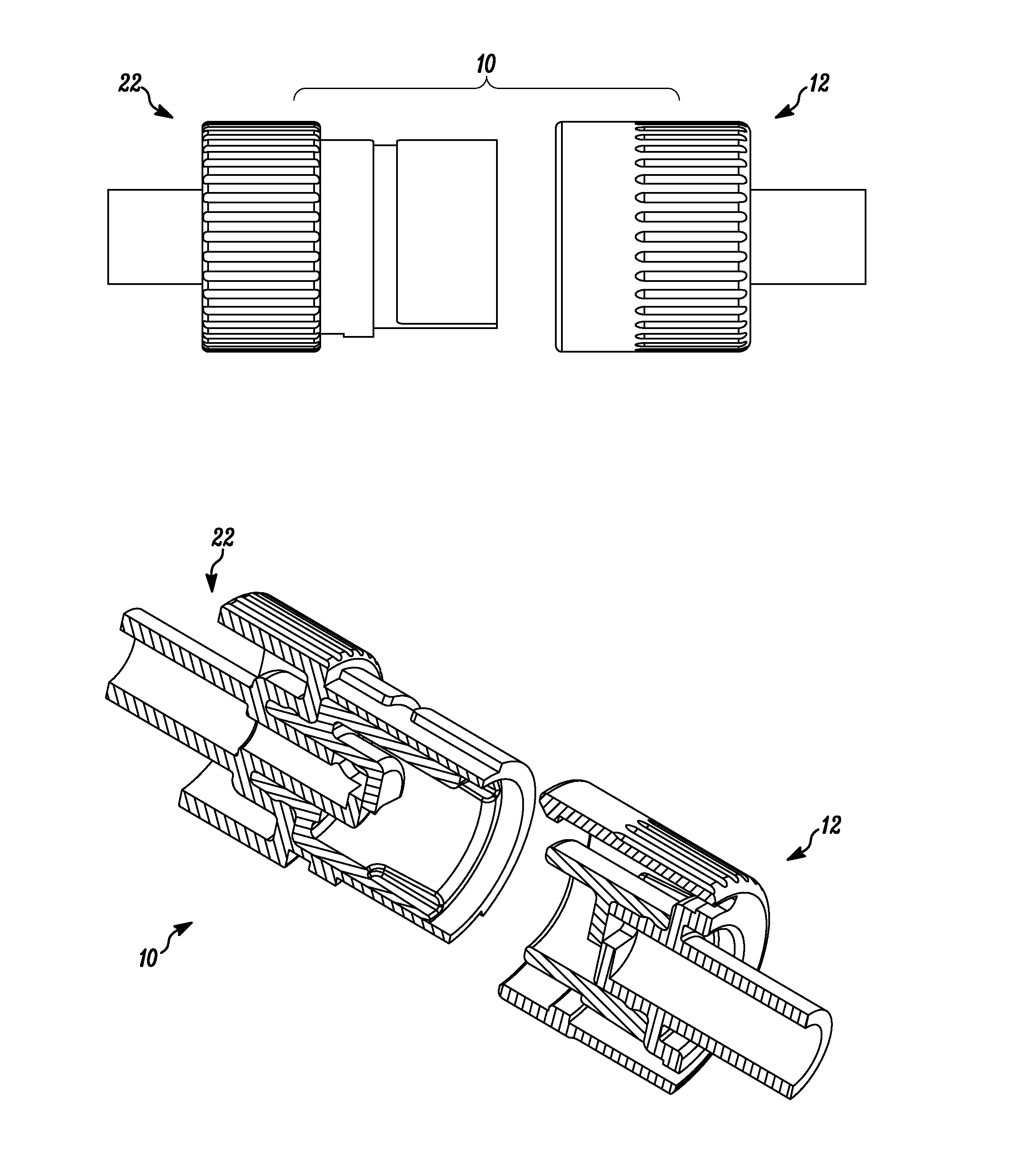
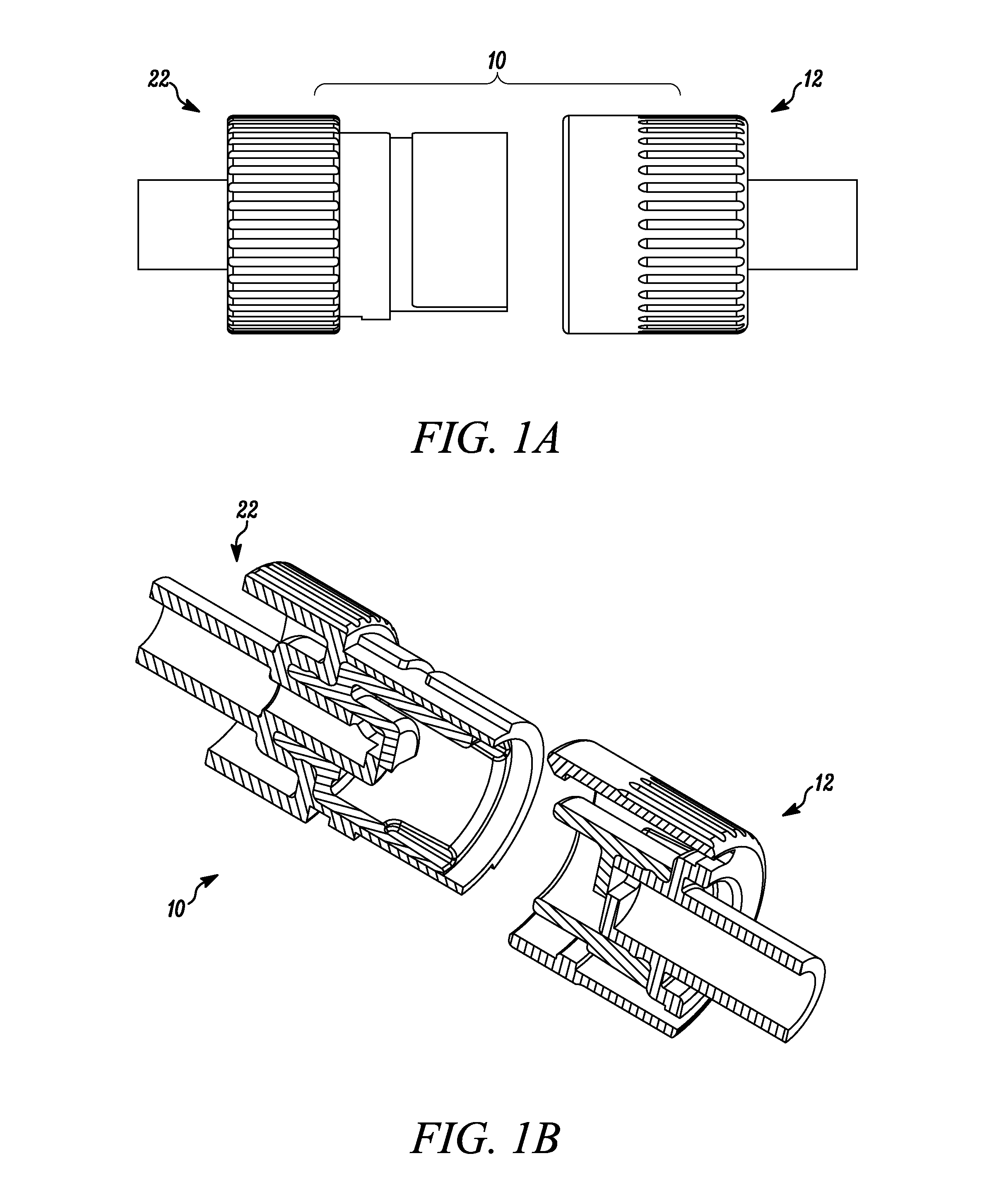
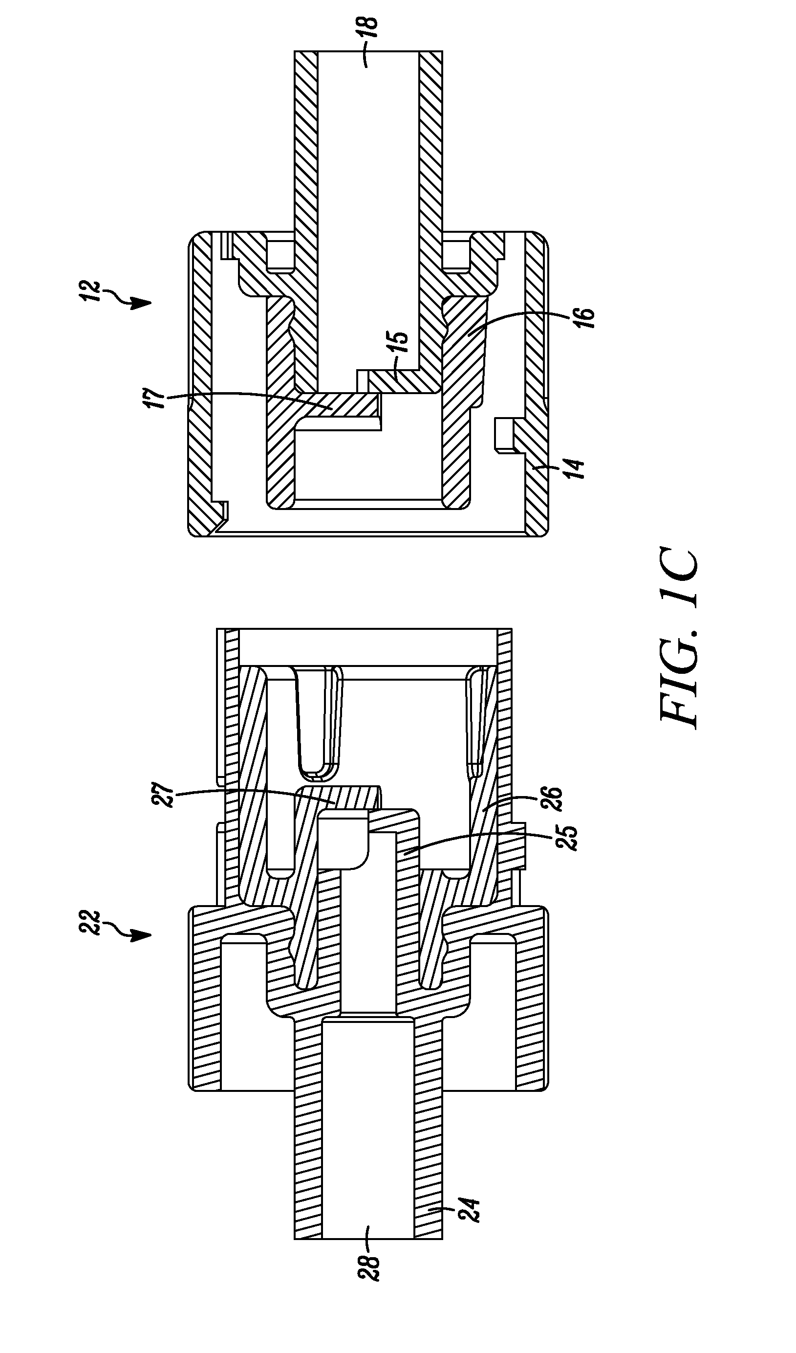
[0028]In FIG. 1A-C, a connector embodying the present invention is indicated generally by the reference numeral 10. The connector 10 comprises a first or female connector 12 and a second or male connector 22. As shown in FIG. 1C, the first connector 12 includes a first fluid passageway 18 for receiving a fluid therein. The second connector 22 includes a second fluid passageway 28 for receiving a fluid therein. The first or female connector 12 includes a first outer portion 14 and the second or male connector 22 includes a second outer portion 24. The first and second outer portions 14, 24 may be formed of any of numerous different materials that are currently known or that later become known for this purpose, such as a suitable plastic, including, for example, a thermoplastic.

[0029]In some embodiments, the outer portion 14 of the first connector 12 and the outer portion 24 of the second connector 22 are complementary. In at least some embodiments, the first connector 12 is configure...


PUM

PropertyMeasurementUnit
shrinkageaaaaaaaaaa
coloraaaaaaaaaa
dimensionaaaaaaaaaa

Abstract

A connector for transferring a fluid includes a first connector and a second connector. Each connector includes a first outer portion including a first obstructive portion and defining a first fluid passageway for receiving a fluid therein. Each connector further includes a first central nozzle coupled to the first outer portion. The central nozzle includes a first engagement member. The first central nozzle is movable between a first position and a second position with rotation of the first outer portion. In the first position, the first obstructive portion and the first engagement portion substantially overlap to impede fluid flow through the first fluid passageway. In the second position, at least one of the first engagement member and the first obstructive member is displaced to allow fluid flow through the first fluid passageway.

Description

CROSS-REFERENCE TO RELATED APPLICATIONS[0001]This patent application claims the benefit under 35 U.S.C. §119(e) of co-pending U.S. Provisional Application Ser. No. 61 / 375,393, filed Aug. 20, 2010, and co-pending U.S. Provisional Application Ser. No. 61 / 377,285, filed Aug. 26, 2010, both of which are entitled “Clean Connector And Related Method”, and are hereby expressly incorporated by reference as part of the present disclosure.FIELD OF THE INVENTION[0002]The present invention relates to fluid connectors and methods of transferring fluids or other material, and more particularly, relates to fluid connectors and methods for transfer of fluids in a manner that maintains the transferred fluid clean, aseptic, sterile, or in another desired condition.BACKGROUND INFORMATION[0003]A typical fluid connector includes a male connector that is received within a female connector to place the two connectors in fluid communication with each other. The male and female connectors may be threadedly ...

Claims


Application Information

Patent Timeline
Patent Type & Authority Applications(United States)
IPC IPC(8): F16L37/00B23P19/00
CPCF16L2201/44F16L37/36A61M2039/1027A61M39/10Y10T29/49826Y10T137/87925Y10T137/9029
Inventor PY, DANIEL
Owner PY DANIEL
Why Eureka
Try Eureka