
Light emitting diode

a technology of light-emitting diodes and diodes, which is applied in the direction of basic electric elements, electrical apparatus, and semiconductor devices, can solve the problems of inconsistent with the demand for more environmentally friendly illumination devices, and the need for frequent replacement of lamps, and achieve the effect of enhancing heat dissipation efficiency and light-emitting efficiency

Active Publication Date: 2012-02-23
SUZHOU LEKIN SEMICON CO LTD
View PDF2 Cites 39 Cited by
  • Summary
  • Abstract
  • Description
  • Claims
  • Application Information

AI Technical Summary

Benefits of technology

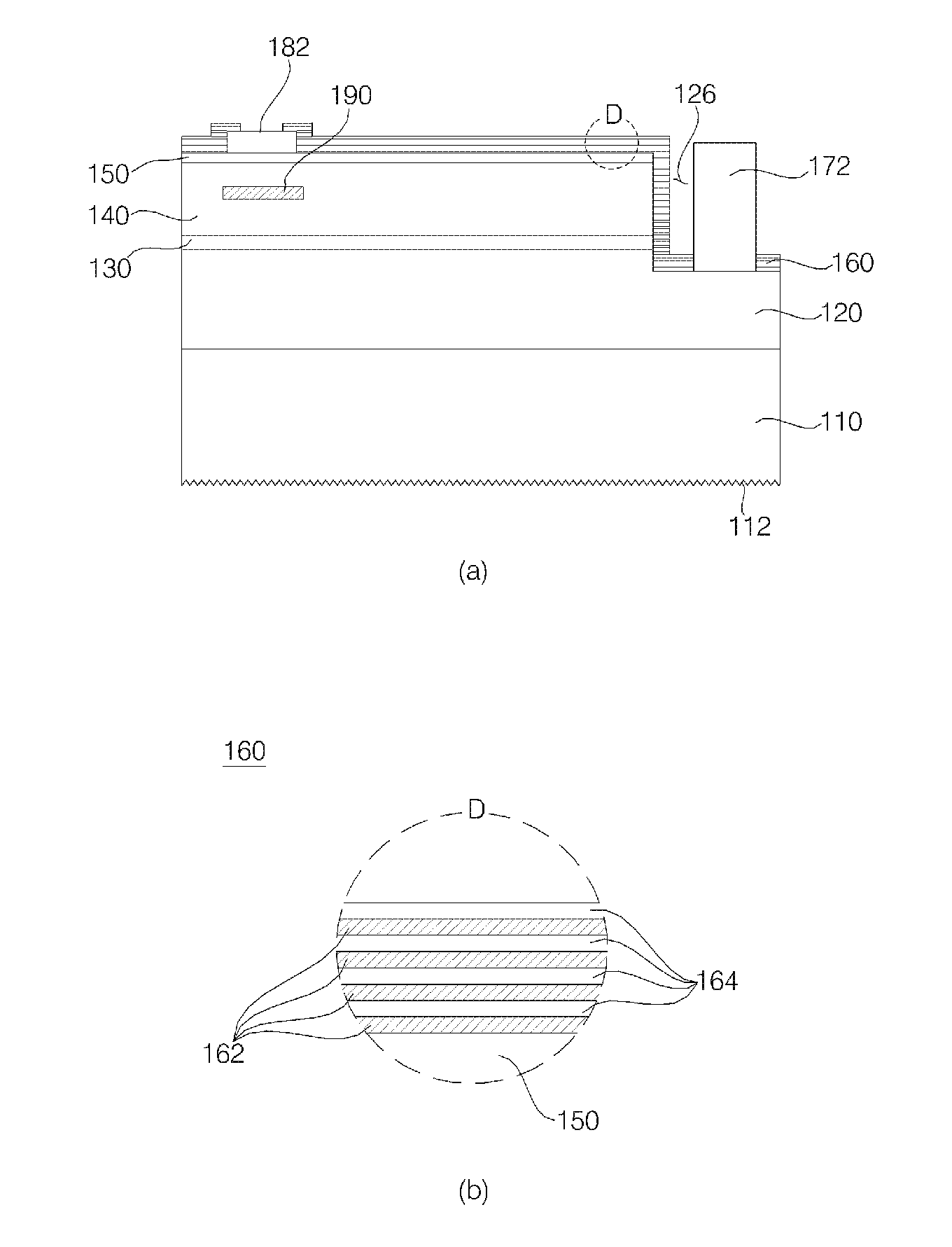
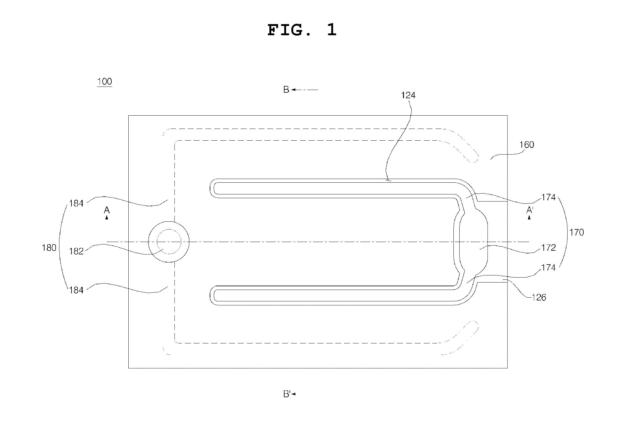
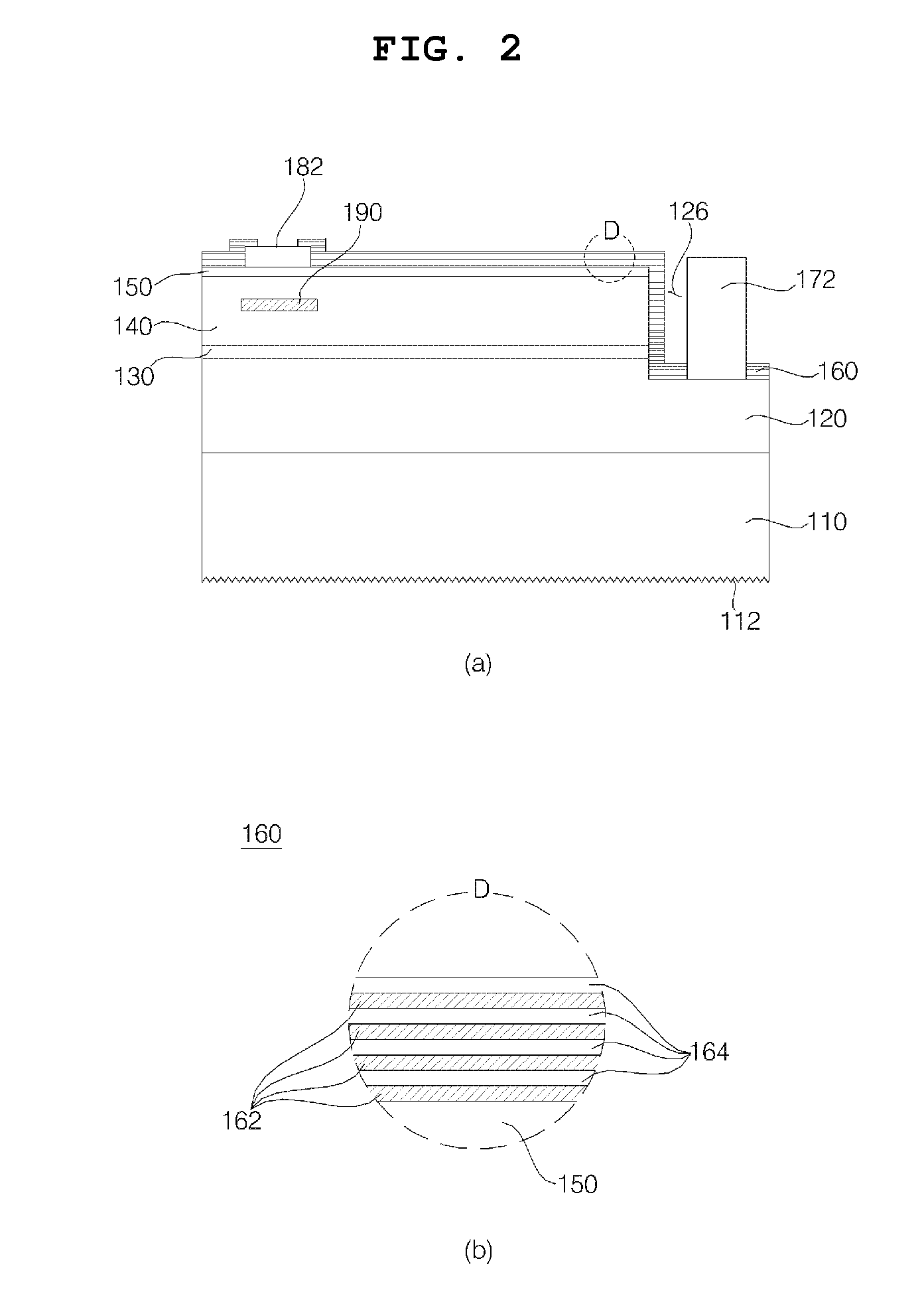
[0009]Embodiments provide A light emitting diode configured to prevent separation of an electrode and to achieve an enhancement in light emission efficiency while securing protection of the light emitting device.
[0011]When the light emitting device is of a flip-chip type, provision of the first reflection layer formed on the outer surface of the light emitting device may achieve an enhancement in light emission efficiency and an enhancement in heat dissipation efficiency.

Problems solved by technology

Fluorescent lamps are required to be frequently replaced due to occurrence of a dark spot, short lifespan, etc.
Furthermore, they are inconsistent with demand for more environmentally friendly illumination devices due to use of fluorescent materials.

Method used


Image

  • Light emitting diode
  • Light emitting diode
  • Light emitting diode

Examples


Embodiment Construction

[0025]Reference will now be made in detail to embodiments, examples of which are illustrated in the accompanying drawings. However, the present disclosure may be embodied in many different forms and should not be construed as limited to the embodiments set forth herein. Rather, these embodiments are provided so that this disclosure will be thorough and complete, and will fully convey the scope of the disclosure to those skilled in the art. The present disclosure is defined only by the categories of the claims. In certain embodiments, detailed descriptions of device constructions or processes well known in the art may be omitted to avoid obscuring appreciation of the disclosure by a person of ordinary skill in the art. Wherever possible, the same reference numbers will be used throughout the drawings to refer to the same or like parts.

[0026]Spatially-relative terms such as “below”, “beneath”, “lower”, “above”, or “upper” may be used herein to describe one element's relationship to an...


PUM


Abstract

A light emitting diode is disclosed. The disclosed light emitting diode includes a light emitting structure including a first semiconductor layer, a second semiconductor layer, and an active layer interposed between the first and second semiconductor layers, a first electrode electrically connected to the first semiconductor layer, a second electrode electrically connected to the second semiconductor layer, and a first reflection layer disposed on the second semiconductor layer. The first reflection layer includes at least a first layer having a first index of refraction and a second layer having a second index of refraction different from the first index of refraction. The first reflection layer is further disposed on a side surface of the second electrode and a portion of an upper surface of the second electrode.

Description

CROSS-REFERENCE TO RELATED APPLICATION[0001]This application claims the priority benefit of Korean Patent Application No. 10-2010-0107149, filed on Oct. 29, 2010 in the Korean Intellectual Property Office, the disclosure of which is incorporated herein by reference.BACKGROUND[0002]1. Field[0003]Embodiments relate to A light emitting diode, and more particularly to A light emitting diode capable of achieving an enhancement in light extraction efficiency, and preventing peeling-off and separation of an electrode when the light emitting device is of a flip-chip type for easy heat dissipation.[0004]2. Description of the Related Art[0005]Fluorescent lamps are required to be frequently replaced due to occurrence of a dark spot, short lifespan, etc. Furthermore, they are inconsistent with demand for more environmentally friendly illumination devices due to use of fluorescent materials. For this reason, fluorescent lamps are gradually being replaced by other light sources.[0006]Among light ...

Claims


Application Information

Patent Timeline
Patent Type & Authority Applications(United States)
IPC IPC(8): H01L33/60
CPCH01L33/38H01L2224/13H01L33/20H01L33/46H01L33/145H01L33/42H01L33/62
Inventor KIM, SUNGKYOONCHOO, SUNGHOJU, HYUNSEOUNG
Owner SUZHOU LEKIN SEMICON CO LTD
Learn More